


12
107031
VENT-FREE NATURAL GAS COMPACT FIREPLACE
VMH10TNB
®
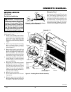
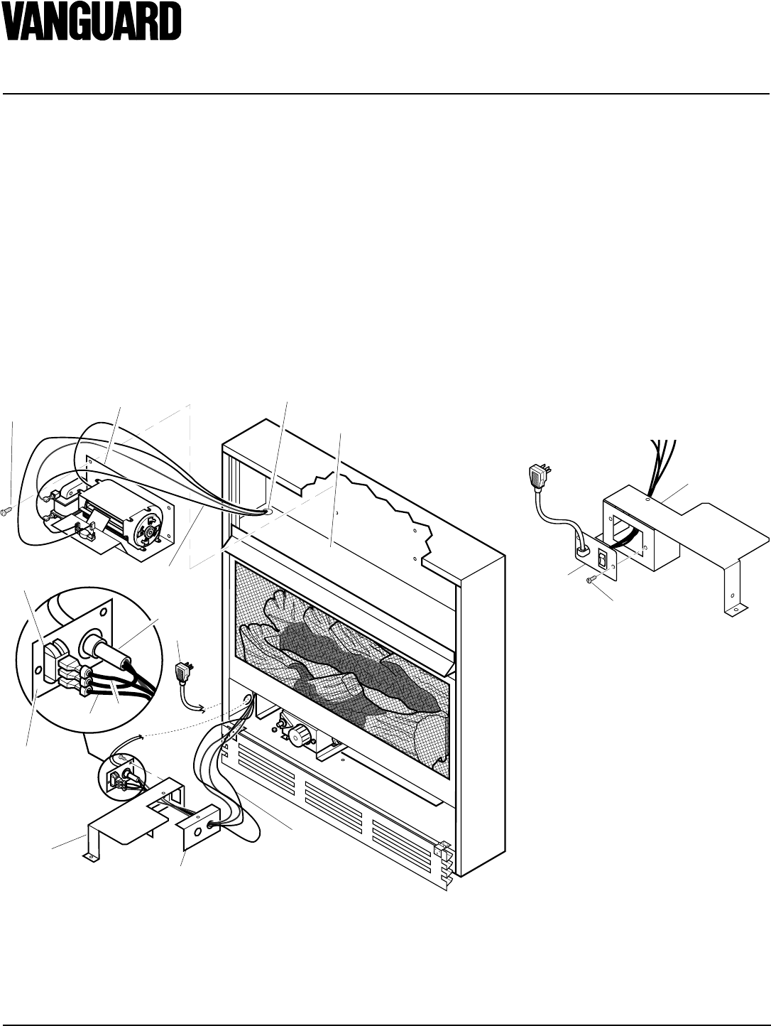
4. Carefully disconnect green and white
wires at their insulated connectors.
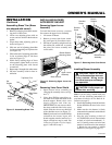
5. In top of the heater cabinet, locate the
four mounting holes on the outer cas-
ing. Align these four holes with those
on the blower bracket assembly. Attach
blower bracket assembly to the outer
casing with 4 #10 screws provided (see
Figure 18).
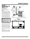
Figure 18 - Installing Blower Bracket Assembly
6. Route the wire harness through the
hole in left side of baffle. Pull wire
harness through lower opening above
where the valve shield was removed.
(see Figure 18).
7. Insert the 4 wire harness into one of the
round holes in the rear of the valve cover
shield and through the rectangular hole
in the front of shield (see Figure 18).
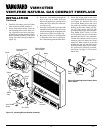
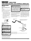
8. Reconnect red wire to switch position
3. Reconnect blue wire to switch posi-
tion 1. Reconnect green and white wires.
Figure 19 - Installing Switch Plate to Valve
Cover Shield
Switch
Plate
Screw
Valve Cover
Shield
INSTALLATION
Continued
9. Install the switch plate on the valve
cover shield with 2 #10 screws provided
(see Figure 19). Reinstall the valve
cover shield. Route power cord out of
the cabinet by inserting it through the
bushing on the outer casing (see Fig-
ure 18). Plug fan kit into 120-Volt
grounded power supply and test opera-
tion.
Note:
When switch is in the
AUTO position, the fan will start after
the heater has run for a few moments.
The fan will continue to run for several
moments after the heater has been
turned off. When switch is in the ON
position, the fan will run until turned
to OFF. Reinstall upper louver assem-
bly and hood if previously removed,
(see Figure 16, page 11). Close lower
louver door.
3
2
1
Wire
Harness
Blower Bracket
Assembly
Screw
Power
Cord
Valve Cover
Shield
Box Cover
Wire
Harness
Switch
Plate
Switch
Baffle
Wiring Routing
Hole in Baffle
Blue
Red