


11
107031
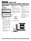
OWNER’S MANUAL
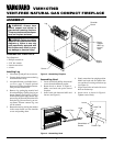
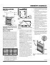
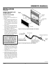
Assembling Brass Trim (Brass
trim shipped with mantel)
1. Remove packaging from three remain-
ing pieces of brass trim.
2. Locate two adjusting plates with set
screws, and two shims in the hardware
packet.
3. Align shim under adjusting plate as
shown in Figure 15.
4. Slide one end of adjusting plate/shim
in slot on mitered edge of top brass trim
(see Figure 15).
5. Slide other end of adjusting plate/shim
in slot on mitered edge of side brass
trim (see Figure 15).
6. While firmly holding edges of brass
trim together, tighten both set screws
on the adjusting plate with slotted
screwdriver.
7. Repeat steps 1 through 6 for other corner.
8. Set brass assembly aside for later in-
stallation.
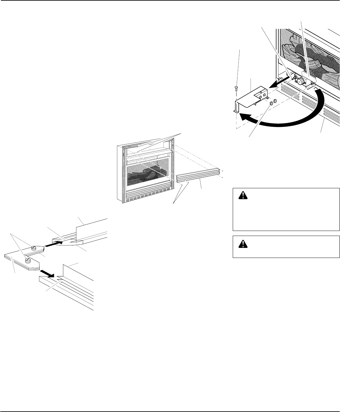
Figure 15 - Assembling Brass Trim
INSTALLATION
Continued
Side Brass
Trim
Top Brass Trim
Mitered
Edge
Shim
Set
Screws
Adjusting
Plate
Slot
Slot
Continued
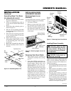
INSTALLING BLOWER
ACCESSORY GA3400T
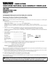
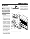
Removing Upper Louver
Assembly
To install the blower accessory, you must
first remove the upper louver assembly.
1. Lift screen off heater.
2. Remove 4 screws from louver assem-
bly (see Figure 16). Save these screws.
3. Pull louver assembly straight out from
the cabinet. Be careful not to scratch
the paint. Set louver assembly and
screws aside.
Figure 16 - Removing Upper Louver As-
sembly
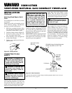
Removing Valve Cover Shield
1. Open bottom louver assembly by
swinging the assembly down (see Fig-
ure 17).
2. Using short Phillips screwdriver, re-
move the screw under the center of the
branch support. Rotate valve cover
shield clockwise and slide out.
IMPORTANT:
Do not remove shoul-
der screw on the left side of valve cover
shield. Slide the valve cover shield off
of the shoulder screw (see Figure 17).
Note:
If you do not have a short Phillips
screwdriver, the screen, logset, and
branch support must be removed so a
longer screwdriver may be used. See
Connecting Fireplace To Gas Supply,
page 15 and follow step 2.
Figure 17 - Removing Valve Cover Shield
Installing Blower Assembly
CAUTION: Label all wires
prior to disconnection when ser-
vicing controls. Wiring errors
can cause improper and danger-
ous operation.
CAUTION: Verify proper op-
eration after servicing.
Note:
If you are using a mantel with your
heater, use the following instructions. If
your heater is built-in, see For Built-In In-
stallation on page 13.
1. Install snap bushings found in hardware
kit into both holes in rear of valve cover
shield.
2. Make sure the wire harness is firmly
connected to the terminals on the blower
bracket assembly.
3. Note the wire locations on back of
AUTO/OFF/ON switch. The terminals
on back of switch are numbered 1, 2,
and 3. Carefully remove red wire from
terminal 1 and blue wire from terminal
3. Black wire can remain on middle
terminal 2 (see Figure 18, page 12).
Upper Louver
Assembly
Brass Screws
Blower Bracket
Mounting Holes
1
2
Remove
Screw
Valve
Cover
Shield
Shoulder
Screw
Branch
Support
Snap
Bushings
Bottom Louver
Assembly