SS-SVX09A-EN 57
Installation
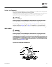
Suction Line Thermostat
Each unit ordered with variable air volume controls (digit 9 in the model number) is shipped with
a suction line thermostat (6S63) that must be field installed.
Locate the thermostat close to the expansion valve bulb on a slightly flattened portion of the suction
line. The thermostat must be securely fastened to the suction line and a field provided
thermoconductive grease must be applied to the area to ensure good heat transfer.
ƽ WARNING
Hazardous Voltage!
Disconnect all electric power, including remote disconnects before servicing. Follow proper
lockout/tagout procedures to ensure the power can not be inadvertently energized. Failure to
disconnect power before servicing could result in death or serious injury.
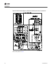
Before installing any connecting wiring, refer to Figure 3 to Figure 8 for the electrical access
locations provided on the unit. Wire the suction line thermostat in accordance with the field
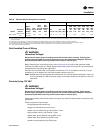
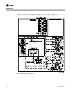
connection diagram in Figure 27. Refer to Table 9 (AC Conductors) for wiring specifications.
Insulate the suction line, where the thermostat is mounted, to isolate it from the surrounding air.
Night Setback
ƽ WARNING
Hazardous Voltage!
Disconnect all electric power, including remote disconnects before servicing. Follow proper
lockout/tagout procedures to ensure the power can not be inadvertently energized. Failure to
disconnect power before servicing could result in death or serious injury.
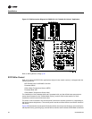
If night setback operation is desired, connect a set of normally open contacts (field provided) to the
appropriate terminals on the terminal board (7TB7), in the unit’s control panel. Remove the factory
installed jumper at the terminal board when making the final wiring termination. Refer to the field
connection diagram in Figure 27 for details.
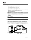
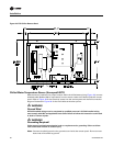
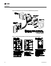
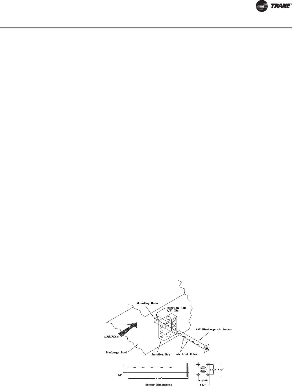
Figure 26. 6RT3 Discharge Air Sensor Assembly


