


ALL phases of this installation must comply with NATIONAL, STATE AND LOCAL CODES
IMPORTANT — This Document is customer property and is to remain with this unit. Please return to service information
pack upon completion of work.
Installer’s Guide
3. Avoid locating the unit where condensation and freezing
of defrost vapor may annoy the customer. For instance,
installing the unit under a bedroom, kitchen, or picture
window may be annoying to the customer since conden-
sate and fog will occur during the defrost cycle.
4. Avoid locating the unit under the eaves or other over-
head structures as sizeable icicles may form and the unit
may be damaged by these falling icicles.
B. LOCATION AND PREPARATION
OF THE UNIT
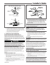
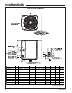
1. When removing unit from the pallet, notice the tabs on
the basepan. Remove tabs by cutting with a sharp tool as
shown on page 2, Figure 2, and slide unit off of pallet.
2. The unit should be set on a level support pad at least as
large as the unit base pan, such as a concrete slab. If this
is not the application used please refer to application
bulletin “Trane APB2001-02”.
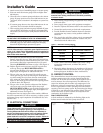
3. The support pad must NOT be in direct contact with any
structure. Unit must be positioned a minimum of 12"
from any wall or surrounding shrubbery to insure
adequate airflow. Clearance must be provided in front of
control box (access panels) and any other side requiring
service access to meet National Electrical Code. Also, the
unit location must be far enough away from any struc-
Heat Pumps
2TWA0, 2TWA2
These instructions do not cover all variations in
systems nor provide for every possible contingency to
be met in connection with installation. All phases of
this installation must comply with NATIONAL, STATE
AND LOCAL CODES. Should further information be
desired or should particular problems arise which are not
covered sufficiently for the purchaser’s purposes, the matter
should be referred to your installing dealer or local distributor.
A. GENERAL
The following instructions cover 2TWA Heat Pump Units.
NOTICE:
These outdoor units may be used with indoor units
equipped with Thermostatic Expansion Valve or Accutron™
Flow Control Check Valve (F.C.C.V.) assembly for refrigerant
flow control only.
Check for transportation damage after unit is uncrated.
Report promptly, to the carrier, any damage found to the unit.
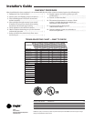
To determine the electrical power requirements of the unit,
refer to the nameplate of the unit. The electrical power
available must agree with that listed on the nameplate.
The Weathertron
®
Heat Pump has been designed and
manufactured to withstand and operate in severe winter
conditions. However, there are precautionary steps which
should be taken at the time of installation which will help
assure the efficient operation of the unit. It is recom-
mended that these precautions be taken for units
being installed in areas where snow accumulation and
prolonged below freezing temperatures occur.
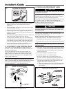
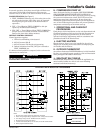
1. Units should be elevated 3 to 12 inches above the pad or
rooftop, depending on local weather. This additional
height will allow better drainage of snow and ice (melted
during defrost cycle) prior to its refreezing. This should
prevent a build-up of ice around the unit which occurs
when unit is not elevated. Insure that drain holes in
unit base pan are not obstructed preventing
draining of defrost water.
2. If possible, avoid locations that are likely to accumulate
snow drifts. If not possible, a snow drift barrier should be
installed around the unit to prevent a build-up of snow
on the sides of the unit and should be of sufficient
distance from the unit to prevent restriction of airflow to
and from the unit. Also allow for proper maintenance
space. The barrier should be constructed of materials
which will blend in with the building design.
1
5 FT. ABOVE UNIT-UNRESTRICTED
2TWA2-IN-1A
18-BC51D3-2