Owner’s Manual
For professional use only
ProFinish C-100 Gun
Model Number 773-400
Parts List
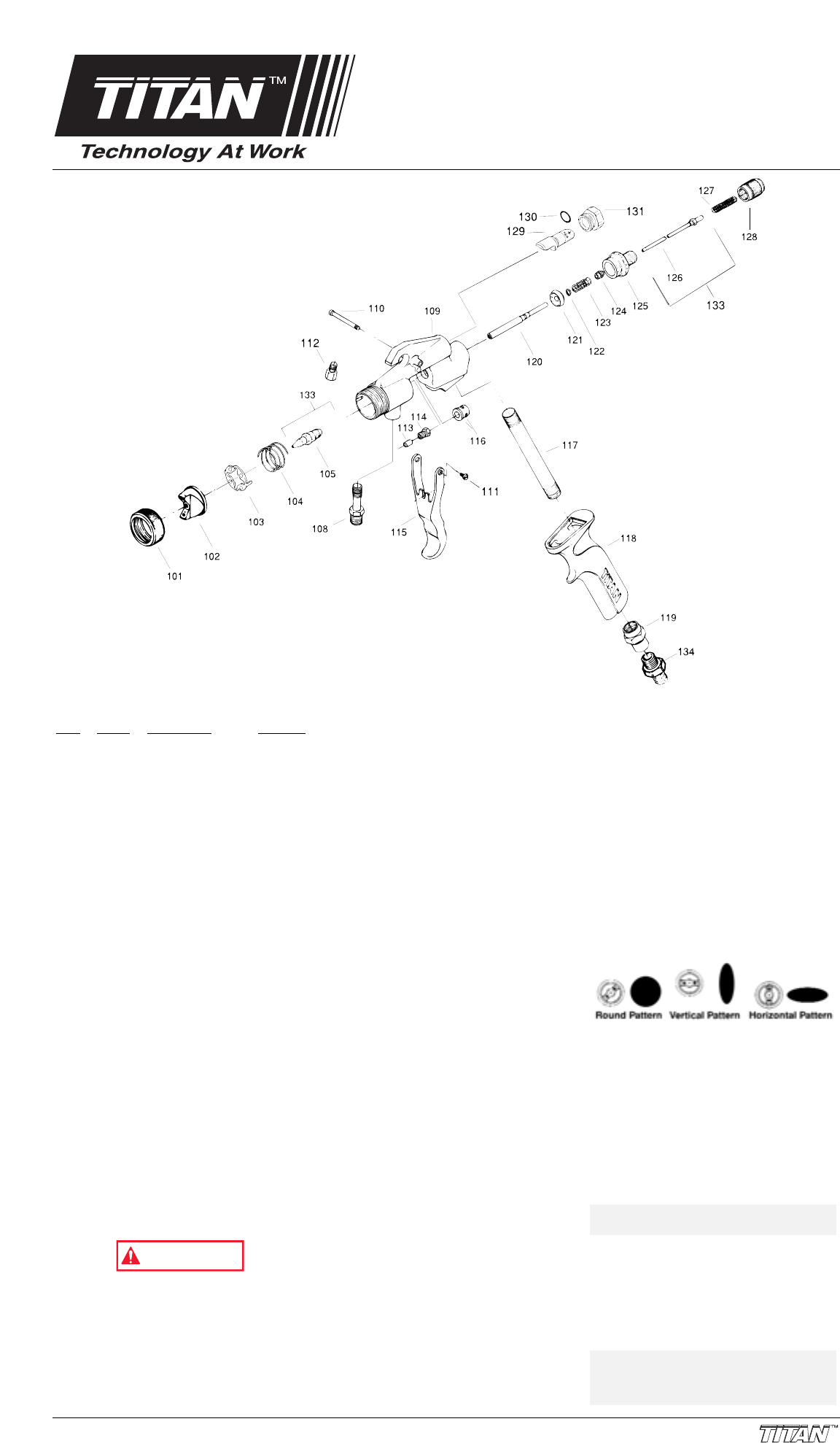
Item Part # Description Quantity
101 773-003 Retaining Ring.......................1
102 773-960 Air Cap “OA”..........................1
103 773-132 Spring Plate...........................1
104 773-168 Air Cup Spring.......................1
105 773-128 Fluid Nozzle “.051”................1
108 490-112 Fluid Fitting............................1
109 773-170 Head......................................1
110 580-018 Pivot Pin................................1
111 580-019 Pivot Screw ...........................1
112 770-179 Plug.......................................1
113 773-005 Packing..................................1
114 773-095 Retainer.................................1
115 773-033 Trigger...................................1
116 773-031 Stem Gland ...........................1
117 773-023 Air Supply Tube.....................1
118 773-167 Handle...................................1
119 773-026 Pipe Adapter .........................1
120 773-027 Trigger Stem .........................1
121 773-029 Trigger Valve.........................1
122 773-028 Retaining Clip........................1
123 773-021 Trigger Spring .......................1
124 773-020 Spring Bushing......................1
125 773-016 Fluid Housing ........................1
126 773-148 Needle Assembly ..................1
127 773-019 Needle Spring .......................1
128 773-017 Adjusting Knob......................1
129 773-067 Air Valve................................1
130 761-722 O-Ring...................................1
131 773-068 Air Valve Housing..................1
313-1078 Label - Fan Adjustment.........1
133 773-153 Needle, Nozzle Set ...............1
134 227-006 Adapter, 1/4”NPTx1/4”NPS...1
773134 HVLP TOOL (not shown)......1
773-135 Brush (not shown).................1
Safety Precautions
Do not use equipment before reading this
section
Never operate this unit unless it is properly
grounded. A fire or explosion hazard is
present when spraying flammable materials.
Please read and understand the following
steps to assure safe operation of your sprayer.
1. Always keep spray area well ventilated.
Always keep the compressor a minimum of
20 feet from spray activity.
2. Always follow the coating or solvent
manufacturer’s safety precautions and
warnings.
3. Never spray flammable materials near
open flames, pilot lights or any other
source of ignition.
4. Always wear spray masks and protective
eye wear while spraying.
5. Never alter or modify any part of this
equipment; doing so could cause it to
malfunction.
6. Never attempt to service or disassemble
the compressor while it is plugged in.
7. Never attempt to clean the exterior of the
compressor while plugged in. CAUTION:
TO REDUCE THE RISK OF ELECTRIC
SHOCK, DO NOT EXPOSE TO RAIN –
STORE INDOORS
8. Never point the spray gun at anyone or
any part of the body.
9. Never leave equipment unattended. Keep
away from children or anyone not familiar
with the operation of spray equipment.
10. Never remove lid of pressure pot without
relieving pressure first.
11. Never exceed 50 psi in pressure pot.
12. Do not use halogenated hydrocarbons in
Titan equipment.
Startup Procedures
Prepare the Paint
1. Prepare the material to be sprayed
according to paint manufacturers
recommendations.
2. Strain the paint before each use. 770-119
Cone Strainer provided.
3. Thin the material to be sprayed with the
recommended solvent. Most materials
need to be thinned to obtain spraying
consistency. To achieve the proper
viscosity for spraying, either a viscosity
cup can be used or trial and error.
4. If a viscosity cup is not available, thin the
materials to a point where you will achieve
a one second interval between drops after
a paint stick has been inserted and
removed from paint.
Gun and Compressor Set-Up
1. With the compressor switch in the off
position, plug into a grounded outlet at
least 20 feet from spray activity.
2. Attach air atomizing hose to compressor.
3. Attach one end of the fluid hose to the gun
and the other end to the pressure pot.
Attach the air hose to the bottom of the
gun. Make sure that everything is secure
before spraying.
Spray Gun Adjustments
The “ProFinish” gun comes equipped with a
.051 fluid nozzle and needle and our “#0A”
medium air cap. Always test your spray pattern
on a test surface before you begin to work.
1. Fan size adjustment is controlled by
turning air cap retainer ring. Clockwise will
increase fan width, counterclockwise will
decrease fan width.
2. Top knob controls the air volume.
Clockwise will decrease air flow.
3. A round, horizontal or vertical fan pattern
can be achieved by rotating air cap as
shown by the diagrams below.
4. A round pattern will require less material
flow than a wide pattern. Lower knob
clockwise will decrease fluid flow; counter-
clockwise will increase fluid flow.
Fluid Nozzle / Needle / Air Cap
Selection
If after all of the appropriate adjustments are
made poor results are obtained, it may be
necessary to change to a different fluid nozzle /
needle or air cap. Refer to our selection chart to
match the appropriate components to the
material being sprayed.
1. To change fluid nozzle and tip remove air
cap (102) and retainer ring (101).
2. Squeeze trigger and with a wrench remove
fluid tip (105). (Use Fluid Tip Tool 773-
134, supplied, not shown)
3. Remove Adjustment Knob (128). Remove
Spring (127) and Needle (126)D.
Reassemble in reverse order 1 thru 3.
NOTE: Never use lubricants containing
silicones. Silicones will adversely
affect spray finishes and is difficult
to remove once on equipment.
NOTE: The smaller the nozzle size the
greater atomization.
WARNING
Form No. 313-1564, REV A © 2000 Titan Tool Inc. All rights reserved. 1


