


TABULAR DATA SHEET
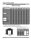
Outdoor Split System Heat Pump 1.5 Thru 5 Tons
MODELS: THJF18* THRU 60
14.5 SEER – R-410A, 1 PHASE
All dimensions are in inches. They are subject to change without notice.
Certified dimensions will be provided upon request.
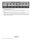
Physical and Electrical Data
MODEL
THJF18
S41S3
THJF24
S41S3
THJF30
S41S3
THJF36
S41S3
THJF42
S41S3
THJF48
S41S3
THJF60
S41S3
Unit Supply Voltage 208-230V, 1 60Hz
Normal Voltage Range
1
187 to 252
Minimum Circuit Ampacity 11.9 17.6 17.3 23.7 26.1 28.8 35.3
Max. Overcurrent Device Amps
2
20 30 30 40 45 50 60
Min. Overcurrent Device Amps
3
15 20 20 25 30 30 40
Compressor Type Scroll Scroll Scroll Scroll Scroll Scroll 2-Stage Scroll
Compressor
Amps
Rated Load 9.0 13.4 12.8 17.9 19.8 28.8 35.3
Locked Rotor 48.0 58.3 64.0 96.7 115.0 115.0 118.0
Crankcase Heater No No No No No No No
Factory External Discharge Muffler Yes Yes Yes Yes Yes Yes Yes
Factory External Check Valve NoNoNoNoNoNoNo
HS Kit Required with TXV
4
No No No No No No No
Fan Motor Amps Rated Load 0.7 0.8 1.3 1.3 1.3 1.3 1.3
Fan Diameter Inches 24 22 24 24 24 24 24
Fan Motor
Rated HP 1/10 1/8 1/4 1/4 1/4 1/4 1/4
Nominal RPM 825 1075 850 850 850 850 850
Nominal CFM 2000 2000 3900 3900 3900 3800 3800
Coil
Face Area Sq. Ft. 15.72 19.17 23.58 23.58 23.58 23.58 23.58
Rows Deep 1111122
Fin / Inches 22 22 22 22 22 18 18
Liquid Line Set OD (Field Installed) 3/8 3/8 3/8 3/8 3/8 3/8 3/8
Vapor Line Set OD (Field Installed) 3/4 3/4 3/4 3/4 7/8 7/8 1-1/8
Unit Charge (Lbs. - Oz.)
5
6 - 15 7 - 14 9 - 14 10 - 9 10 - 14 14 - 2 14 - 2
Charge Per Foot, Oz. 0.62 0.62 0.62 0.62 0.67 0.67 0.75
Operating Weight Lbs. 145 145 176 193 198 248 290
1. Rated in accordance with ANSI/AHRI Standard 110-2002, utilization range “A”.
2. Dual element fuses or HACR circuit breaker. Maximum allowable overcurrent protection.
3. Dual element fuses or HACR circuit breaker. Minimum recommended overcurrent protection.
4. See Hard Start Kit Accessory Installation Manual for Hard Start Kit part number for each model.
5. The Unit Charge is correct for the outdoor unit, matched indoor coil, and 15 feet of refrigerant tubing. For tubing lengths other than 15 feet,
add or subtract the amount of refrigerant, using the difference in length multiplied by the per foot value.
B
C
A
Unit
Model
Dimensions
(Inches)
Refrigerant Connection
Service Valve Size
A
1
1. Including Fan Guard.
B C Liquid Vapor
18
28 34 34
3/8”
3/4”
24 40 29 29
30 40 34 34
36 40 34 34
42 40 34 34
7/8”48 40 34 34
60 40 34 34
MAC-222
ECN 5287-MA 121005