


D200-69-00 1 I56-1145-05R
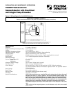
2100AT Photoelectronic
Smoke Detector with Fixed Heat
and Integral Temp-3 Sounder
INSTALLATION AND MAINTENANCE INSTRUCTIONS
3825 Ohio Avenue, St. Charles, Illinois 60174
1-800-SENSOR2, FAX: 630-377-6495
Specifications
Diameter: 5.5 inches (140 mm)
Height (including mounting bracket): 2.05 inches (52 mm)
Weight: 7.5 oz. (210 g)
Operating Temperature Range 32° to 100°F (0° to 38°C)
Operating Humidity Range: 10% to 93% Relative Humidity, Noncondensing
Latching Alarm: Reset by momentary power interruption
Audible Signal: 85 dBA minimum when in alarm or with supply polarity reversed
Heat Sensor: 135°F Fixed Temperature Electronic Thermistor
Electrical Ratings
System Voltage (nominal): 12 or 24 VDC
Minimum: 8.5 VDC
Maximum: 35 VDC
Maximum Ripple Voltage: 30% of nom. Voltage (peak to peak)
Standby Current: 50
µ
A average, 100
µ
A maximum
Alarm Ratings: 29 mA typical at 12 VDC, 63 mA typical at 24 VDC, 100 mA maximum
(If used, the RA400Z Remote Annunciator operates within the specified detector
alarm currents.)
Reset Voltage: 1.8 VDC minimum
Reset Time: 0.6 seconds maximum
Start-up Time: 30 seconds maximum (after 60 sec. reset)
EOL Relay: A77-716B, 12/24 VDC
Special Considerations: NOTE: Only one detector per zone shall be used, unless when in alarm the panel
switches the zone to a reverse polarity, non-current limited power supply. For
panels that do not provide this feature, a reversing relay, such as System Sensor’s
RR-2, may be used. When utilized with the 2100AT, it allows for more than one de-
tector to be utilized on a loop. Some panels may require the use of programmable
outputs. Refer to System Sensor literature for further information on the RR-2.
The 2100AT detector shall not be mixed with other 2-wire detectors on the same
zone.
–Due to the built-in temporal pattern, use this detector only with a non-coded
power source.
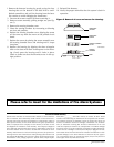
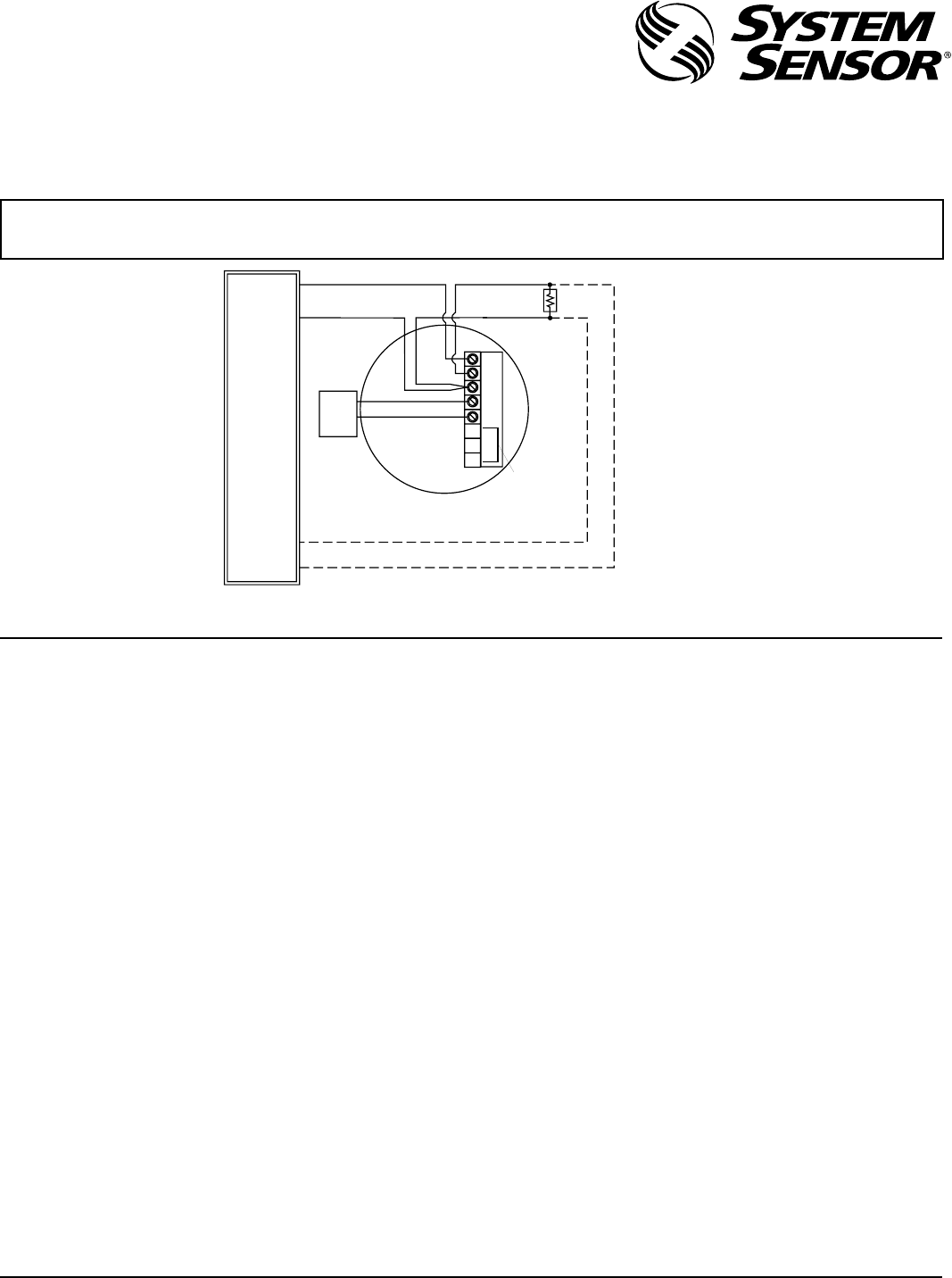
Figure 1. Wiring diagram for the 2100AT detector:
A78-2336-15
IMPORTANT: OBSERVE POLARITY
Polarity must be observed on the power and remote annunciator connections.
OPTIONAL CLASS A WIRING
EOL
INITIATING
LOOP
UL LISTED
COMPATIBLE
CONTROL
PANEL
+
–
+
+
–
A+
RA400Z
REMOTE
ANNUNCIATOR
A
-
+
–
P
W
R
NOT
USED
NOTE: Only one detector per zone shall be used, unless when in alarm the panel switches
the zone to a reverse polarity, noncurrent-limited power supply. The 2100AT
detector shall not be mixed with other 2-wire detector types on the same zone.