BP1620, BP1628 & BP1640 Granulators Page 17 BP1600
CAUTION!
The knives mounted on the rotor and also located at the front and rear of the
cutting chamber are extremely sharp. Always wear heavy gloves and exercise
care when working in the cutting chamber.
Wipe out the inside of the hopper and upper cutting
chamber. Carefully inspect the interior of the cutting
chamber for foreign material or debris. Slowly turn the
rotor by hand to verify that it rotates freely and without
obstruction or contact between the rotor and bed knives.
Before closing the cutting chamber, check the chamber to
insure that nothing has been left inside the machine. Rotate
the hand crank counter-clockwise until the cutting chamber
is fully closed. Remove the discharge transition or bin, by
sliding out from under the screen chamber..
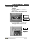
Lower the screen chamber until it comes to rest
Remove the screens and place them on their side. Wipe out
the screen chamber and transition. Once cleaned, place the
screen back into position. Raise the screen chamber and
tighten the fasteners to hold the screen chamber and cutting
chamber securely closed. Connect the fan transition
(optional) or replace the bin to prepare the machine for
operation. Position and connect any optional accessory
equipment such as fans, conveyors, and separators. Ensure
all tubing joints are securely clamped and supported.
Make certain all electrical connections are properly made
and supported between accessories and the control
enclosure. (Refer to the wiring diagrams for wire and
terminal connections.)
Open the sheave guard (LH) by removing the fasteners
attaching the cover. Check the belts for proper tension and
alignment (refer to Section 9-2). Upon completion, close
the sheave guard by placing the cover back into position,
insert all of the fasteners originally removed, and tighten
them fully.
3-4 Electrical Service Connections
Carefully check the diagrams packed with the machine. All
internal wiring has been done at the factory and safety


