BICYCLE/FRAME INSTRUCTION GUIDE
TRANSITION CARBON - ALL MODELS
Congratulations! The Specialized bicycle you have chosen is among
the finest of advanced composite products available in cycling.
Carbon fiber is a very special material that requires particular care
during assembly, storage and riding. This installation guide contains
instructions and warnings, plus torque specifications.
Please read the following instructions. If you have any doubt regarding
your mechanical ability and/or installation of this product, visit your
local authorized dealer. Specialized recommends that components be
installed on the frame using a torque wrench, by a qualified mechanic.
Please read the following Warnings. Because the failure to follow any
Warning may result in a catastrophic failure of the frame, resulting in
serious personal injury or death, this phrase may not be repeated in
connection with each Warning.
To ensure the best assembly possible and to prevent any damage
to the components or frame, follow all torque specifications. Please
refer to the specific owner’s manual for mating component’s correct
torque specifications. If the mating component’s recommended torque
exceeds the frame’s recommended torque, use the lower torque spec.
Due to torque considerations, not all components will be compatible.
Warning! Failure to follow the torque specifications in this
installation guide will void the warranty, but most importantly
may result in damage to the frame which may not be visible.
If the frame is damaged, this can result in loss of structural
integrity, which may result in serious personal injury or death.
Bicycle components such as a handlebar, handlebar stem, seat post,
saddle, brakes, all must be compatible with each other, the frame
and the intended use. Any doubt regarding compatibility should be
discussed with your local authorized Specialized retailer.
Warning! When placing the frame and/or bicycle in a repair
stand, clamp the stand using a frame clamp specifically designed
for thin-wall carbon tubes, for example the Park Tools 100-X4 Ex-
treme Range Clamp. Clamping the frame with a standard clamp
can cause damage to the frame that may or may not be visible.
The Specialized Transition frames require a proprietary seat post,
available in 3 different setbacks. The Transition seat post system allows
for an extremely wide seat tube angle range which is infinitely variable
inside that range, to help the rider achieve the optimal riding position.
To help the Transition frame achieve its aerodynamic benefits, the
frame was designed with a very short seat post vertical adjustment
range. Proper installation of the Transition Seat Post requires the use
of a dedicated Transition Fit Kit tool set.
This setup (fitting and cutting) MUST be performed by an authorized
Specialized dealer to ensure that the seat post is cut to the optimal
length, to maximize the +/- vertical adjustment range.
INSTALLING THE SEAT POST & SADDLE
THIS INSTALLATION GUIDE CONTAINS IMPORTANT INFORMATION.
PLEASE READ CAREFULLY AND STORE IN A SAFE PLACE.
Warning!
Due to the nature of the seatpost having to be
cut to a specific length, the seat post is NOT marked with a
minimum insertion line. For proper seatpost insertion, ensure
that the seat post extends below the minimum insertion hole
located at the back of the seat tube area. Extension beyond
the minimum insertion hole in the frame can result in failure.
Warning! Do not grease the seat tube surface that contacts
the seat post. Grease reduces the friction that is critical to
proper seat post grip. Remove any grease from the surfaces
of the seat tube and seat post.
TECH TIP:
Specialized recommends the application of carbon
assembly compound between the seat tube and post to increase
friction. Recommended compounds can be found at www.tacx.com.
See your authorized Specialized retailer if you have any questions.
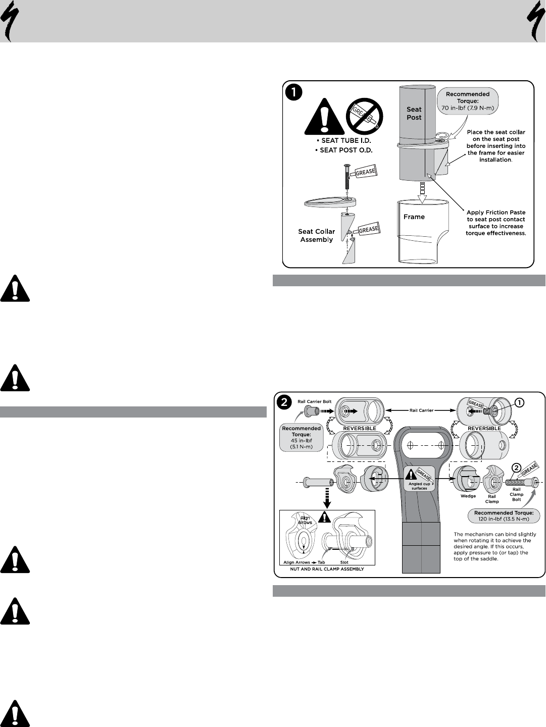
Tighten seat collar bolt to recommended torque of 70in-lbf (7.9 N-m).
See fig.1 for proper grease and assembly compound application zones.
GENERAL WARNINGS
FORK: Do not remove the small bumpers on the side/back of the fork
legs. These are to protect the frame from fork contact.
REAR WHEEL: Due to variables in tire manufacture, heat expansion,
foreign debris, etc. Specialized recommends a minimum rear wheel-
to-frame clearance of 2mm. The UCI requires sufficient clearance such
that a credit card must fit between the rear tire and the back of the seat
tube.
Thread the horizontal dropout screws in or out to fine-tune the alignment
and fore-aft position of the wheel. To ensure that the rear wheel can’t slip
forward in the dropouts under torque, make sure that the rear axle butts
up against the dropout screws before tightening the Quick-Release.
Contact between the frame and tire can cause wear and damage to the
frame, which can result in failure.
ADJUSTING THE SEAT POST
• Install the seat post into the seat tube (fig.1).
• Install the rail clamp carrier in the chosen direction (reversible) and
tighten the alloy rail carrier bolt (bolt #1, fig.2).
• Grease the contact surfaces and bolt threads of the rail clamp
Mechanism, then install it in the rail clamp carrier.
• Install the saddle in the rail clamp mechanism.
• Adjust the saddle to the desired height, angle and fore-aft position.
• Torque the rail clamp bolt to the recommended setting. To avoid
damage, the nut tab must be properly lined up with the rail clamp
slot (bolt #2, fig.2).
• Torque the seat collar bolt to the recommended setting (fig.1).
Warning! Exceeding the specified recommended torque limit
can result in damage to the seat post and/or frame.
