


Installation Instructions
GENERAL
These instructions cover the installation of the accessory wall
mounting kit. The kit is provided for mounting cooling only,
multi-split, and heat pump units to a wall due to space
limitations.
IMPORTANT: Read these installation instructions thoroughly
BEFORE starting installation.
Refer to Table 1 for kit contents and usage.
Table I--KIT CONTENTS AND USAGE
MOUNTING
KIT PART USAGE KIT CONTENTS*
NUMBER
53DS900077
53DS900078
All 018,024 Sizes
Plus
38HDF/538E- F 030
38QRF/638Q- F030
AIIElse
030 - 060
2 - Long Bracket
Section
2 - Horizontal Bracket
Section
2 - Angled Bracket
Section
6 - Wall Lag Bolts
6 - Lag Bolt Washers
6 - Wall Lag Bolt
Shields (Anchors)
4 - Mounting Feet
Bolts (1 in.)
4 - Mounting Feet
Locknuts
10 - Bracket Assy.
Locknuts
10 - Bracket Assy.
Bolts (1/2 in.)
10 - Bracket Assy.
Lockwashers
*The contents for both kits are the same: however, the items are different
sizes for specific applications.
SAFETY CONSIDERATIONS
Installation of this equipment can be hazardous due to system
pressures, electrical components and equipment location. Only
trained, qualified installers and service technicians should install.
start up and service this equipment. Observe all applicable
precautions.
Improper installation, adjustment, alteration, service,
maintenance, or use can cause explosion, fire. electrical shock, or
other conditions which may cause personal injury or property
damage. Consult a qualified installer, service agency, or your
distributor or branch for information or assistance. The qualified
installer or agency must use factory-authorized kits or accessories
when modifying this product. Refer to the individual instructions
packaged with kits or accessories when installing.
Follow all safety codes. Wear safety glasses and work gloves. Use
quenching cloth for brazing operations. Have fire extinguisher
available. Read these instructions thoroughly and follow all
warnings or cautions attached to the unit. Consult local building
codes and National Electrical Code (NEC) for special
requirements.
Recognize safety information. This is the safety-alert symbol
Z_. When you see this symbol on the unit and in instruction
manuals, be alert to the potential for personal injury.
Understand the signal words DANGER, WARNING,
CAUTION, and NOTE. These words are used with the
safety-alert symbol. DANGER identifies the most serious
hazards which will result in severe personal injury or death.
WARNING signifies hazards which could result in personal
injury or death. CAUTION is used to identify unsafe practices
which may result in minor personal injury or product and
property damage. NOTE is used to highlight suggestions which
will result in enhanced installation, reliability, or operation.
ELECTRICAL SHOCK HAZARD
Failure to follow this warning could result in personal
injury or death.
Before installation, always check to be sure main power to
system is OFE
INSTALLATION
1. Unpack accessory from carton. Check to be sure contents
are not damaged or missing. See Table 1.
2. Select mounting location on the wall. The location must
allow for use of wall studs for mounting security. Check
local building codes and building construction to ensure
that there is adequate wall strength to support the mounted
unit. The location must also allow for condensate drainage
from the unit. Be sure this drainage does not cause a
problem for the area beneath the unit.
IMPORTANT: Ensure that the unit will be mounted at least 6 in.
from the wall for proper airflow. Also ensure that there will be at
least 6 in. of airflow clearance on the coil end and 18 in. on the
compressor end for service access.
IMPORTANT: Do not drill new holes in the bracket assembly in
order to move the unit closer to the wall.
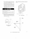
3. Use the enclosed long bracket sections as a template for
marking the mounting kit location on the wall. Both long
bracket sections must line up with the middle and coil end
mounting feet of the unit. See Fig. 1.