


English9
INSTALLATION AND EXTERNAL CONNECTION
installation and external connection
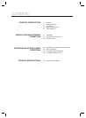
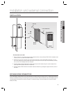
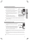
INSTALLATION
- On a doorframe or the wall
Drill a 1/2-inch (12.7 mm) hole onto the center of the doorframe or the wall where SSA-S1000 is installed, which
makes room for the cable of the reader module.
Drill two 0.3-inch (7.62 mm) holes: one on the point of 0.39 inch (10 mm) horizontally to the right, 1.74 inch
(44.4 mm) vertically up from the center hole, and one on the point of 0.33 inch (8.5 mm) horizontally to the left,
0.3 inch (7.62 mm) vertically down from the point.
Insert the reader module cable into the center hole and secure the module using two screws inserted in the
upper right and the bottom left corner, respectively.
Insert the bezel of SSA-S1000 into the reader module and attach it by pressing the upper and lower corner of
the bezel.
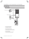
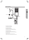
BYPASS DIODE CONNECTION
If you connected an inductor (door lock or alarm device) to the output relay, there should occur a voltage surge while the
inductor was between turning on and turning off. If you do not connect a reverse diode to the relay, the voltage surge will
cause damage to the electric circuit of the controller. To reduce this surge, it is recommended to connect the bypass
diode to the relay.
1.
2.
3.
4.
6-32 hole
6-32 or M3 Screws
1/2” hole
6-32 hole
Reader
Module