


Kit Components
MSB-C2 (Pack C)
(For wiring MSB units)
Parts List
Part
Qty
MSB Communication cable
Terminal connector 2
Instruction Sheet
1
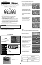
Connecting Multiple MSB-M Units
1) On the master MSB, one connector
is connected to the terminal connector
and the other one is connected to the
MSB Communication cable.
2) When 2 MSB boards are used a
MSB Communication cable will be
installed between the master MSB
board and the second MSB. The open
connector will have the Terminal
connector installed on both MSB
boards.
A maximum of 5 MSB boards can
be connected to each other.
The terminal connector is
connected on the terminal MSB
which has an open connector.
1
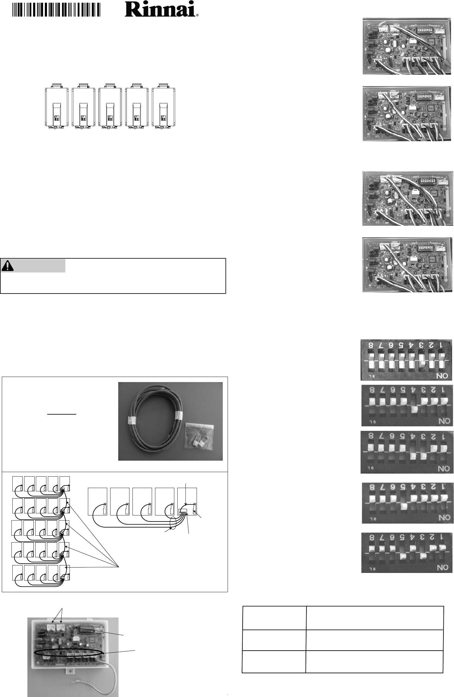
3) Set No 3 switch on the master MSB
to ON. The LED light 6 should turn ON
conrming the connection.
Communication Cables B
Water Heater
Control
Communication Cable A
Control Board
MSB Communication cable (MSB-C2)
(13.1 ft, 4 m)
U306-1032(00)
5) Set No 3 and No 4 switches on the
third MSB board to ON.
The LED light 6 should turn ON
conrming the connection.
6) Set the No 5 switch on the fourth
MSB board to ON.
7) Set No 3 and No 5 switches on the
on the fth MSB board to ON.
MSB-C2
Note:
•
Up to 5 water heaters can be connected together using
the MSB-M and MSB-C1 kits.
United States & Canada: For use with Rinnai Tankless Water
Heaters (except for models V53e, V53i and R63LSe which must
use pressure activation valves, PVA).
•
Disconnect all water heaters from their power source before carrying out
the following installation procedures.
NOTE: The front cover panels of each water heater must be removed prior
to completing the following installation procedures.
WARNING
Please contact Rinnai if you have further questions on the
applicable water heater models.
•
•
When over 5 water heaters are connected together,
MSB-M units are connected using MSB-C2 kits.
•
If multiple MSB-M are used, then at least three water heaters
should be connected to each MSB-M.
Ex: With 7 water heaters, one MSB-M should control 4 water
heaters and the other MSB-M should control 3 water heaters.
070 00012 32069 4
Master MSB board
2nd MSB board
5th MSB board (Terminal MSB)
2nd to 4th MSB board
LED6
LED 1 ~ 5
(See MSB-C1 instruction)
Stand alone
Solid
O
EXPLANATION
Working with multiple MSB boards
LED 6
Indicator light (LED 6) on the Control Board indicates the status as
follows:
4) Set No 4 switch on the second MSB
to ON. The LED light 6 should turn ON
conrming the connection.
The LED light 6 should turn ON
conrming the connection.
The LED light 6 should turn ON
conrming the connection.
Master
2nd
3rd
4th
5th
Manifold Electronic Control System
Installation Instructions
Communication cable connectors
NOTE:
When viewing the installed MSB board, the dip switch will be as
shown below (upside down).