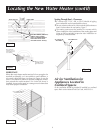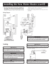
Must maintain
adequate service
and maintenance
accessibility.
Range of degrees
available for vent
pipe installation.
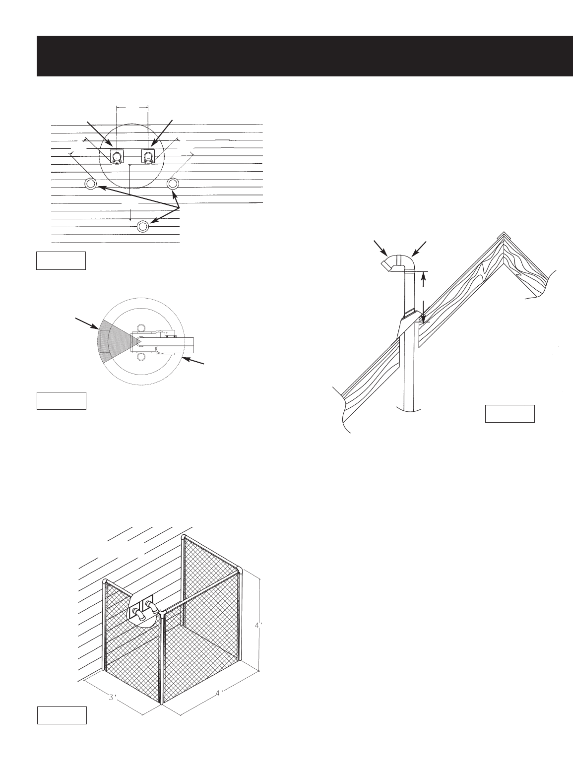
Figure 5
Figure 7
Locating the New Water Heater (cont’d)
9
Figure 6
Air for Ventilation for
Appliances Located in
Confined Spaces
Air for ventilation should be provided if installed in a confined
space. Refer to the National Fuel Gas Code, ANSI Z223.1.
Figure 4
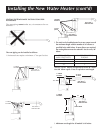
WIRE FENCE
When the water heater outlet terminal is low enough to be
touched accidentally, or is accessible to small children, a
wire mesh chain link fence (as shown in Figure 6) may be
used. Care should be taken to maintain adequate ventila-
tion around the outlet terminal. If a chain link fence is
installed, it must not be used as a storage area for items that
may block proper ventilation.
NOT TO BE USED AS
A STORAGE AREA
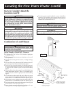
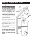
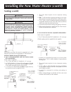
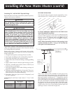
Venting Through Roof – Clearances
•
0″ clearance for 3″ PVC, ABS, or CPVC Schedule 40 piping
from combustible and noncombustible surfaces.
•
The vent exhaust outlet and air inlet terminals shall terminate at
least 18 inches above the roof surface. Figure 7.
•
The
venting system must be installed in a manner which
allows inspection of the installation of the venting pipes and
joints as well as periodic inspection after installation as
required by ANSI Standards.
18
″
24″
NATURAL DRAFT (GRAVITY)
DIRECT VENT, POWER
VENT, OR POWER DIRECT
VENT APPLIANCE INLET
AND/OR OUTLET VENT(S).
VENT OUTLET AIR INTAKE
18″
6
1
⁄
2
″ MIN.
24″ MAX.
18″
45˚
45° VENT CAP
W/SCREEN
90° STREET ELL


