


TELEVISION
IN1 IN2 IN3 IN4 OUT1
AUDIO
VIDEO
AUDIO
VIDEO
AUDIO
VIDEO
AUDIO
VIDEO
AUDIO
VIDEO
OR
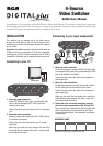
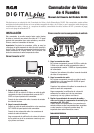
INSTALLATION
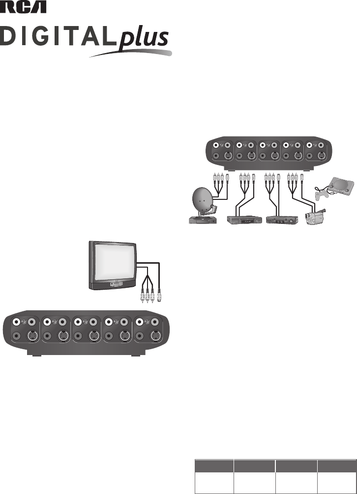
This switcher lets you manage up to four video sources
through one video input on your TV. The back panel of the
switcher has four inputs and one output. Connect the switcher
to your TV first.
Important: Use either composite video (the yellow jacks) or
S-Video on all of your connections. If all of your components
(including your TV) offer S-Video connections, use all S-Video
connections. Otherwise, use all composite video connections.
Connecting to your TV
Congratulations on your purchase of the DH4VS Video & Stereo Audio Switcher. This switcher accepts stereo analog audio
and composite video and S-Video, allowing you to manage your audio/video components (such as satellite receivers, cable
converters, DVD players and gaming consoles) on a single set of TV inputs.
INPUT 1 INPUT 2 INPUT 3 INPUT 4
REFERENCE CHART
Note which component you connect to each input.
4-Source
Video Switcher
DH4VS User's Manual
1. Make the video connection.
Connect EITHER an S-Video cable or a composite video
cable to the corresponding OUT1 VIDEO jack on the
switcher's back panel.
Connect the other end of the cable to the TV's video input
jack.
2. Make the audio connection.
Connect a stereo audio cable to the OUT1 AUDIO jacks on
the switcher's back panel.
Connect the other end of the cable to your TV's audio
input jacks.
Make sure you match the color coding at the end of the
cables with the color coding on the jacks—match red with
red and white with white.
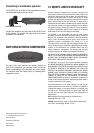
1. Make the video connection.
For the first component, connect EITHER an S-Video cable
or a composite video cable to the corresponding IN1 VIDEO
jack on the switcher's back panel.
Connect the other end of the cable to the component's
video output jack.
2. Make the audio connection.
For the first component, connect a stereo audio cable to
the IN1 AUDIO jacks on the switcher's back panel.
Connect the other end of the cable to the component's
audio output jacks.
Make sure you match the color coding at the end of the
cables with the color coding on the jacks—match red
with red and white with white.
3. Repeat the video and audio connection steps for
your other input components on IN2, IN3 and IN4.
As you connect your components to the input jacks, note
which component you have connected to each jack in
the space provided below. This information is important
to have handy.
VCRDBS
CAMCORDER
DVD
VIDEO
GAME
(Audio/Video
or
S-Video
hook-up
only)
IN1 IN2 IN3 IN4 OUT1
AUDIO
VIDEO
AUDIO
VIDEO
AUDIO
VIDEO
AUDIO
VIDEO
AUDIO
VIDEO
OR OR OR OR
Connecting to your input components