


R
R
R
October 26, 2006
7014-083C
Page 17
CB1200-I Pellet Insert
7
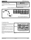
Appliance Set-Up
A. Rear Shroud Installation
2. Rear vent installations
Parts Required:
Part 811-0680, Rear Shroud Kit.
Part 811-0690, Rear Vent Kit
Includes: Rear Vent Adapter and fastener package.
Tools Required:
Electric drill, 1/8" drill bit, Phillips screw driver, /8"
wrench & 7/16" wrench, (7/16" socket wrench & high
temperature silicone adhesive are also required for rear
vent installations).
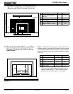
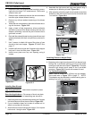
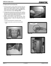
Knock-Out Rear
V
ent Access
Outside Air V
ent
Pipe Access
Right Corner
Left Corner
Top Vent Opening
Left Corner
Filler Piece
REAR SHROUD TOP
VENT PART 811-0650
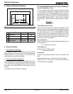
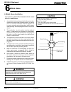
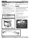
1. Top Vent Installations
Parts Required:
Part 811-0680, Rear Shroud Kit.
Includes: Six galvanized steel shroud pieces, two cover
plates and fastener package.
Part 811-0650, Rear Shroud Top Vent
Includes: Vent pipe and two 1/4 - 20 x /4" bolts with nuts.
Part 811-0660, " Top Vent Adapter or Part 811-0670, 4”
Top Vent Adapter
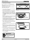
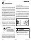
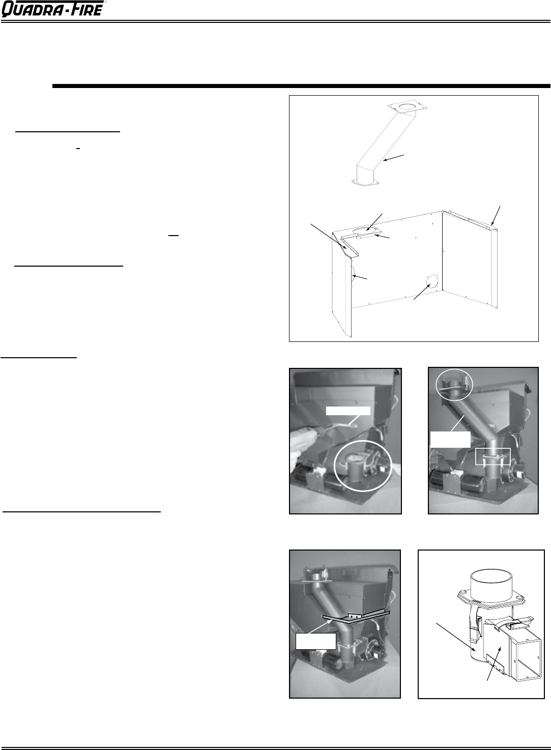
Vertical Exhaust
Transition Pipe
Top Vent Adapter
Figure 17.5
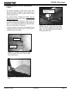
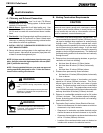
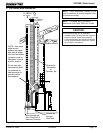
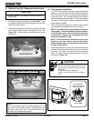
1. Remove the top vent adapter from the vertical exhaust
transition pipe. Figures 17.2 and 17.5.
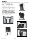
2. Use 2 screws to attach left corner ller piece of rear
shroud to the insert hopper. Figures 17.1 and 17.2.
. Use (2) 1/4 - 20 x /4" bolts with nuts to install rear
shroud top vent to the exhaust transition. See boxed
area in Figure 17.3. (Circled area, top vent adapter,
will be installed later).
4. Install the left shroud panel corner at points, 2 screws
into back of hopper and 1 down into the ller piece).
Figure 17.4
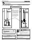
Complete the following procedures, based on
your venting installation, prior to installing
the rear shroud kit. (Note: All photos depict top vent
installation).
Top Vent Installation Preparation
Filler Piece
Left Corner
Piece
Rear Shroud
Top Vent
Figure 17.1
Figure 17.2 Figure 17.3
Figure 17.4