


Panasonic Electric Works Fire & Security Technology Europe AB
Jungmansgatan 12, SE-211 19 Malmö, Sweden
Tel: +46 (0)40 697 70 00 • Fax: +46 (0)40 697 70 99
info-fste@eu.pewg.panasonic.com • www.panasonic-fire-security.com
Fire alarm systems
Addressable manual
call point
3333
• Attractive design compliant with EN54-11
• Test key for routine testing without breaking the glass element
• Protection against accidental operation
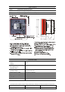
General
The call point has an attractive design
compliant with EN54-11, and is either
surface mounted in the supplied red backbox
or recess mounted in a standard UK single
gang box or a Swedish 65 mm circular
backbox. It has a clip retained front cover
that makes it easy to replace the glass
element and adds security since the clips are
concealed. The frangible element is a glass
element with a protective plastic film. To
operate the call point, the glass element is
pressed until it is broken. This will activate
the built-in microswitch, which will generate
a fire alarm in the c.i.e.
Test key
Routine testing is made with a supplied test
key, without breaking the glass element.
Inserting the test key simulates the breaking
of the glass element. The call point is
automatically reset when the test key is
removed. The test key is also used to
release the security clips for the front cover.
Protective cover
To protect the call point against accidental
operation, a transparent polycarbonate cover
has to be lifted to get access to the glass
element.
Encapsulated circuit
All electronics are encapsulated. Only the
terminal block is accessible from the rear.
LED indicator
An LED on the front cover indicates fire
alarm generated by the call point.
Flashing LED: The LED will flash each
time the c.i.e. communicates with the call
point, until the call point is operated and the
LED is switched on.
Non-flashing LED: The LED is switched
off, until the call point is operated and the
LED is switched on.
Connections / Settings
The COM loop is connected directly to the
call point via a 4-way terminal block. For
COM loop address setting is the address
setting tool 3314 is used. 3314 is also used
to set the call point type and the LED mode:
• NORMAL mode (EBL512 SW version
>
2.0 / EBL128): M.c.p. type 3333.
(Flashing or non-flashing LED is set via
Win512 / Win128.)
• 2330 mode: M.c.p. type 2333
, flashing
LED.
• 2312 mode: M.c.p. type 2333
, non-
flashing LED.
Two flying leads (wires) are connected to
the terminal block, for connection of the
3314 address setting tool's connection cable.
The wires are to be disconnected before the
COM loop wires are connected.
Product applications
Used in the systems EBL512 / 128 / 1000 /
2000 and is intended for indoor use and in
dry premises.