


READ & SAVE THESE INSTRUCTIONS!
INSTALLATION INSTRUCTIONS
Heat-A-Ventlite
®
MODELS: QT-9093 SERIES
IMPORTANT: DO NOT MOUNT OVER TUB
OR IN SHOWER STALL ENCLOSURE.
PRECAUTIONS
• Observe all requirements in this instruction sheet and all markings
appearing on the unit.
• Check all operations of the unit after installation has been completed.
•
The heater housing must be grounded and the wiring must comply
with all local electrical codes.
• The flange of the rough-in housing MUST be flush with the finished
plaster or drywall surface to assure proper and absolutely safe operation.
• If plaster material, paint base or paint is sprayed on the walls or ceiling,
the inside of the housing must be masked off to prevent this material
from entering the housing.
• The switch (furnished) must be wired in accordance with the
wiring diagram.
•
For installation in sloped ceilings up to 12/12 pitch.
•
Ductwork must point up.
PREPARATION
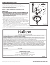
Refer to Figure 1.
1. Loosen two screws holding grille in place. Remove grille and set aside. Remove housing,
switch assembly, hanger bar and mounting brackets from carton.
2. Loosen four (4) screws holding heater power unit in place. Remove heater power unit and
set aside.
MOUNTING TO OPEN JOISTS IN NEW CONSTRUCTION
1. Install hanger brackets in keyhole slots in housing. Insert hanger bar through bracket opposite
blower vent.
2. Refer to Figure 2. Position housing between joists with exhaust vent in desired direction.
Secure side hanger brackets and ends of
adjustable hanger bar to joists with screws or nails.
If joist spacing is greater than 16" O.C., construct
framing to support sides of housing,
(Refer to Figure 3). Position housing against joists
and secure with wood screws through keyhole
slots in housing.
3. Loosen screws securing hanger brackets to
housing and adjust height of housing so that
bottom flange will be flush with finished ceiling.
Tighten screws securely.
4. Attach 4" round duct and run ductwork to the
outside through wall or roof.
WIRING
115-120 volts (20 amp circuit only), 12 gauge wire.
1. Remove desired knockout from junction box and install a box connector (not provided).
2. Refer to Figure 4. Run 120vAC supply wiring to wall switch box. Run wiring from wall switch box to
heater. Five conductors plus ground are required for independent operation of all functions.
3. When a thermostat or timer switch is used, connect at point marked “T” on Figure 4.
4. Make wiring connections using wire nuts. Connect ground wire under ground screw in junction box.
5. Push wiring back into junction box and install junction box cover being careful not to pinch wiring
between cover and housing. Secure cover.
HEATER
SCREWS
FIGURE 1
HEATER
SCREWS
13" DIA.
14" DIA.
FIGURE 3
FIGURE 4
FIGURE 2