


INSTALLATION INSTRUCTIONS
READ & SAVE THESE INSTRUCTIONS!
IMPORTANT: These Ceiling Fan Light Kits are for use with
NuTone Model PFOB-52 only.
CAUTION
1. CAUTION - To reduce the risk of fire and electrical shock,
this light kit should be used only with NuTone fan model
PFOB-52.
2. Read entire instructions carefully before beginning installation.
3. CAUTION - To reduce the risk of electrical shock, disconnect
the electrical supply circuit to the fan before installing the light
kit.
4. All wiring must be in accordance with national and local
electrical codes. If you are unfamiliar with wiring, you should
use a qualified electrician.
MAKING THE CONNECTIONS
NOTE: See fan instructions for connecting house wiring to the
fan. Connect house wiring to the fan before attaching light kit to
the fan. See wiring diagrams on back of this page, titled wiring
wall switches.
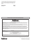
1. Refer to Figures 1. Remove the cover plate from the bottom
of the fan switch housing.
2. Assemble the cover plate to the light kit as shown. Use the
pipe nipple and nuts provided.
3. Locate the two wires in the fan switch housing that have
labels marked “Connect Light Here” or “For Light Use”.
One wire will be white and the second will be black or blue
with or without white tracer. Connect these wires to the wires
coming from the light kit. Assemble the light kit to
the fan using the screws removed in step 1 (one) above.
Re-assemble bottom cover and pendent to the fan. Proceed
to completing the Installation.
COMPLETING THE INSTALLATION
1. Install (1) 100 watt maximum light bulb. Note: Refer to the
guide for maximum size bulb that is printed on the
light fixture.
2. Should light shade begin to buzz, be certain all
thumbscrews are tight.
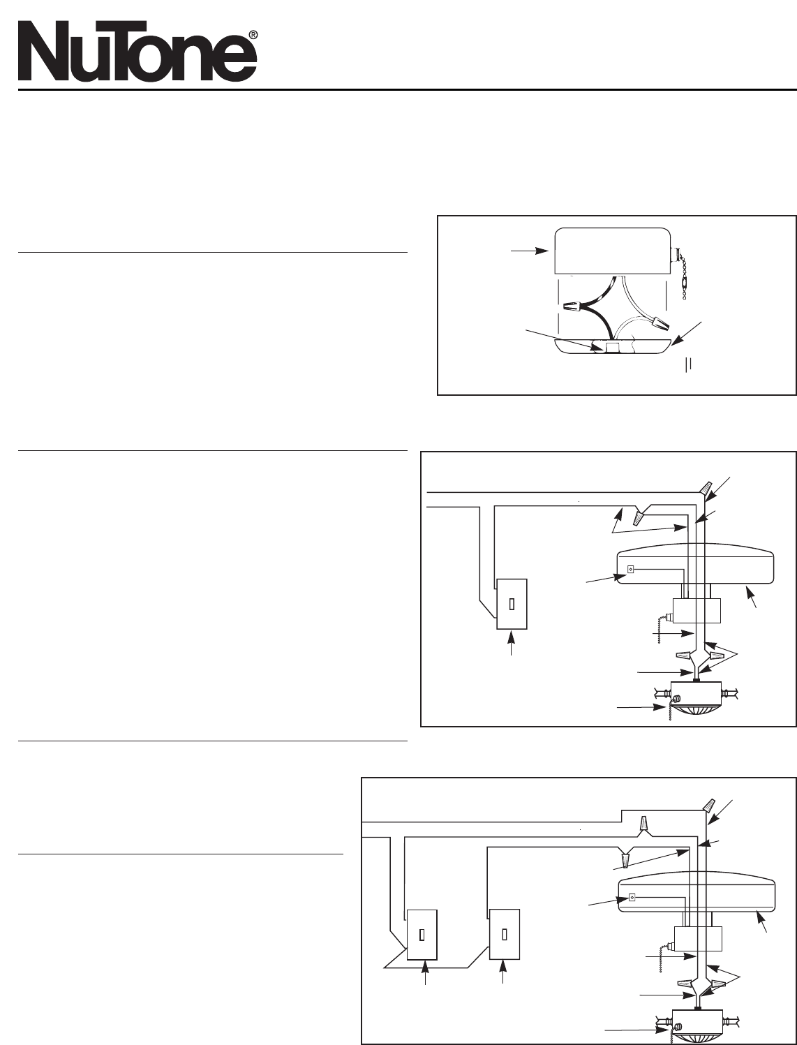
WIRING WITH WALL SWITCHES
The Ceiling Fan and Light Kit can be connected
through wall switches. This can be done in two ways.
Select the type of control desired and wire the unit
according to Figure 2 or Figure 3.
Use one wall switch to control both fan and light.
Individual control of either fan or light is done with the
pull chain switches.Or use two wall switches to
individually control both fan and light – one for the fan
and the second for the light. Pull chain switches on
the fan do not have to be used.
SWITCH
HOUSING
PIPE, NIPPLE,
NUTS, ETC.
COVER PLATE
FIGURE 1
Ceiling Fan Light Kits
Models: PFLK-123 Series
115 VOLT SUPPLY
BLACK WIRE
MOTOR
CONNECTIONS
(NON-ACCESSIBLE)
BLACK WIRE
WITH TRACER
OR BLUE WIRE
BLACK
WIRE
WALL
SWITCH
LIGHT KIT
BLACK WIRE
WITH TRACER
OR BLUE WIRE
WHITE WIRE
WHITE
WIRE
FAN AND LIGHT ON A SINGLE WALL SWITCH
WHITE
WIRES
CEILING
FAN
FIGURE 2
FIGURE 3
115 VOLT SUPPLY
BLACK WIRE
MOTOR
CONNECTIONS
(NON-ACCESSIBLE)
BLACK
WIRE
WALL
SWITCH
FOR FAN
WALL
SWITCH
FOR
LIGHTS
LIGHT KIT
WHITE WIRE
WHITE
WIRE
CEILING
FAN
WHITE
WIRES
FAN AND LIGHT ON SEPARATE WALL SWITCHES
BLACK WIRE
WITH TRACER
OR BLUE WIRE
BLACK WIRE
WITH TRACER
OR BLUE WIRE