


INSTALLATION INSTRUCTIONS
READ & SAVE THESE INSTRUCTIONS!
Recess-Mounted
Door Chime
MODEL: LB-14 SERIES
• Your NuTone Door Chime is designed for two-door
operation. For best results, use NuTone Model 101T
Transformer.
• Handle the door chime carefully as you would any
precision instrument.
• Comply with local wiring codes when installing the
door chime.
• If upon completion of the installation the chime does not
operate, check your installation against these instructions.
If the chime still does not operate, check the pushbutton(s)
for poor contact or loose connections and wiring for
short circuits.
• If chime plungers should ever become sluggish in their
movement, clean the plungers with a nonflammable
cleaning fluid and wipe dry. CAUTION: NEVER OIL
CHIME PLUNGERS.
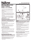
MOUNTING THE FRAME
Refer to Figure 1. The chime mechanism is shipped
mounted in the metal mounting frame. Remove the
cardboard plaster shield and remove the chime mechanism
from the frame by freeing one side and sliding to the side.
NEW CONSTRUCTION
1. Bend or break off the four mounting tabs. Do not bend
tabs inward.
2. Nail the chime mounting frame to a wall stud in the
required location. Position the mounting frame so the
front edge will be flush to the finished wall surface.
3. Complete the wiring connections.
EXISTING CONSTRUCTION
1. Bend out the recess mounting tabs.
2. In the desired location between wall studs, mark around
the mounting frame and prepare a 4
7
⁄8" wide by 7" high
cutout.
3. Insert the frame into the cutout. The recess mounting
tabs go behind the wall. The recess mounting tabs and
the two pairs of tabs on the side of the frame should hold
the frame firmly in position.
4. Complete the wiring connections.
MOUNTING THE DOOR CHIME
1. Install chime to mounting frame after finished wall is
in place.
2. Feed wires through the wiring entrance in the chime's base
plate and make wire connections to the terminal board.
3. Slide the chime mechanism under the cover mounting
brackets and snap chime into frame.
4. Mount chime cover to mounting brackets by using
supplied screws.
WIRING
• Be certain the power has been disconnected at the main
source before making the connections.
• Comply with local electrical code.
• When stapling wires to studs or joists, do not allow staples
to cut through wire insulation.
1. Mount the transformer to a convenient junction box (attic
location not recommended) or circuit breaker box.
2. Connect house power leads to transformer leads: black to
black, white to white.
3. Run 2-conductor, 18 gauge cable from the transformer
screw terminals and from the pushbutton screw terminals
to the chime location.
4. Refer to Figure 2. Bring wires into the mounting frame.
Connect the transformer and pushbutton wires to the
terminal board on the chime base plate.
ELECTRONIC WIRING HOOK-UP FROM DOOR
CHIME TO INTERCOM SYSTEM
1. Run NuTone IW-2 cable (22 gauge twisted-pair cable) from
intercom location to chime.
2. Run wires through wiring hole in chime base plate
and connect to terminals 1 and 2 on volume control
terminal board.
3. Refer to instructions packaged with intercom for
connection to intercom.
FIGURE 1
FIGURE 2
COVER
MOUNTING
BRACKET
SLIDE
CHIME
MECHANISM
FRONT DOOR
PUSHBUTTON
120v AC
WIRING
NUTONE 101T
TRANSFORMER -
USE NUTONE MODEL
301T FOR TWO OR
MORE CHIMES
COMMON
WIRES
REAR DOOR
PUSHBUTTON
TERMINAL
BOARD
CHIME No. 1
TERMINAL
BOARD
CHIME No. 2
18 GAUGE INSULATED
2-CONDUCTOR WIRE
FRONT FRONT
TRANS
TRANS
REAR
REAR