


8
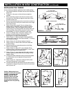
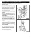
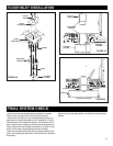
1. Use black rubber connectors and hose clamps to connect intake
and exhaust tubing.
2. Connect intake tubing to intake tube on power unit.
3. Connect exhaust tubing to upper exhaust tube on power unit.
4. Make sure all tubing connections are securely fastened.
5. An optional muffler (Model 392) may be installed to reduce
motor noise.
6. The exhaust should not be vented into a wall, ceiling or concealed
space in the house. Exterior vented exhaust lines should be term-
inated using Model 393 Wall Caps or appropriate louvered
exhaust vents.
POWER UNIT INSTALLATION
FIGURE 26
FIGURE 27
TUBING CONNECTIONS AT POWER UNIT
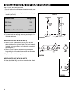
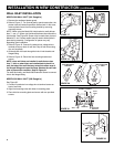
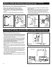
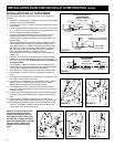
MOUNTING See Figure 25. Also refer to page 3.
1. Locate power unit within six feet of a grounded electrical outlet.
2. Remove mounting bracket from power unit and attach to wall,
following minimum clearances noted in Figure 25. Screws must be
secured into a wall stud or other suitable support.
3. Hang power unit securely on bracket.
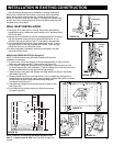
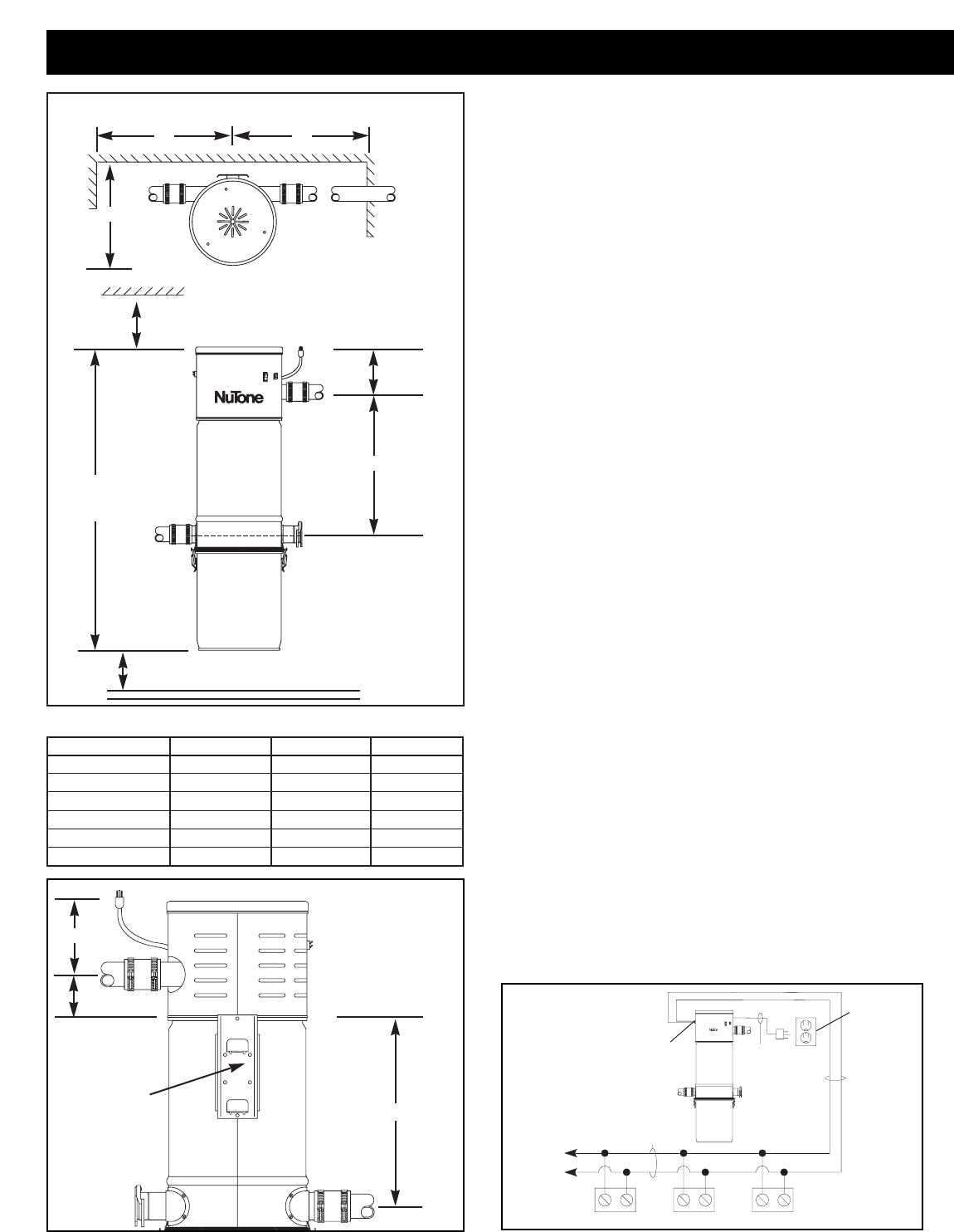
WIRING See Figure 27.
Grounding Instructions – This appliance must be grounded. If it
should malfunction or break down, grounding provides a path of least
resistance for electric current, to reduce the risk of electric shock. This
appliance is equipped with a cord having an equipment-grounding
conductor and grounding plug. The plug must be plugged into an
appropriate outlet that is properly installed and grounded in accordance
with all local codes and ordinances.
Danger –
Improper connection of the equipment-grounding
conductor can result in a risk of electric shock. Check with a qualified
electrician or service person if you are in doubt as to whether the outlet
is properly grounded. Do not modify the plug provided with the
appliance – if it will not fit the outlet, have a proper outlet installed by a
qualified electrician.
This appliance is for use on a nominal 120 volt circuit and has a
grounding plug. Make sure that the appliance is connected to an outlet
having the same configuration as the plug. No adapter should be used
with this appliance.
1. Connect low voltage wire (18 gauge, 2-conductor, Model 376-UL or
376) to crimp connectors located on outside of the power unit.
2. The power unit is equipped with a six foot grounded cord.
Plug cord into 120 volt grounded receptacle.
CONVENIENCE
OUTLET
MOUNTING
BRACKET
INLET INLET INLET
TO
OTHER
INLETS
POWER
UNIT
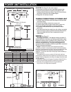
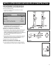
DIMENSIONAL CHART
DIMENSION CV554 CV556 CV570
A11
3
⁄4"11
3
⁄4"15
1
⁄8"
B40
3
⁄8"41
1
⁄4" 39"
C4
3
⁄4"6"4
3
⁄8"
D2
3
⁄8"2
1
⁄2"5"
E17
7
⁄8"18
1
⁄2"20
1
⁄2"
F15
1
⁄2"15
1
⁄2"15
1
⁄2"
FIGURE 25
MINIMUM WALL CLEARANCE DIMENSIONS
18"
18"
BACK VIEW
C
D
F
INTAKE
EXHAUST
CONVENIENCE
OUTLET
12" MINIMUM TO CEILING
FRONT VIEW
C
E
B
OVERALL
HEIGHT
INTAKE
18" MINIMUM ABOVE FLOOR
(MORE IS RECOMMENDED)
A
TOP VIEW
WIRING
MODEL
376-UL
OR
376
(18
1
⁄2) WIRE
POWER
CORD
120 VAC
ELECTRICAL
OUTLET
PUSH-ON
CONNECTORS
®
NOTE: INLET
LEADS CONNECT
TO POWER UNIT
USING PUSH-ON
CONNECTORS
SUPPLIED ON
POWER UNIT