DESCRIPTIONDESCRIPTION
The capacity of the MA3000, GEM-Series and Signature
5500 and SS-P Series control panels may be expanded
through the use of GEM-EZM zone expansion modules.
GEM-EZM4 modules provide up to four additional zones;
GEM-EZM8 modules, up to 8 additional zones. Four-zone
and 8-zone modules may be combined as necessary to
supply the required number of zones. Refer to the installa-
tion instructions for the control panel in use for wiring
requirements for UL-listed applications.
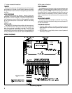
WIRINGWIRING
Wire the expansion zones to the module and the module
to the control panel in accordance with the wiring diagrams
using wire no thinner than #22AWG. Install end-of-line
resistors on all zones even if one or more zones are not
used.
Note:Note: The addition of Zone Expansion Modules will re-
duce the amount of current available at the control panel’s
Auxiliary Power Output terminals.
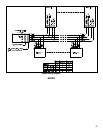
MODULE ASSIGNMENTMODULE ASSIGNMENT
Regardless of how the modules are arranged, the expan-
sion zones are divided into consecutively-numbered
groups of four. Each 4-zone module comprises one group
of zones; each 8-zone module comprises two groups.
Every module must be assigned a unique ‘‘base address’’.
In the case of a 4-zone module, the base address number
is the same as its group number. For the 8-zone module,
the base address number will be the lower of its two group
numbers. Note that (a) groups must be numbered con-
secutively (that is, missing numbers are not permitted); and
(b) no two modules may be numbered alike.
Example. Two GEM-EZM8s and one GEM-EZM4 are used
to provide 20 expansion zones:
Groups 1 & 2 Group 3 Groups 4 & 5
GEM-EZM8GEM-EZM8 GEM-EZM4GEM-EZM4 GEM-EZM8GEM-EZM8
Base Addr ‘‘1’’ Base Addr ‘‘3’’ Base Addr ‘‘4’’
The base address is assigned to the module by proper
selection of Address Jumpers JP1-JP5 (to the right of the
LED) in accordance with Table 1. Also refer to the Zone
Wiring Diagram.
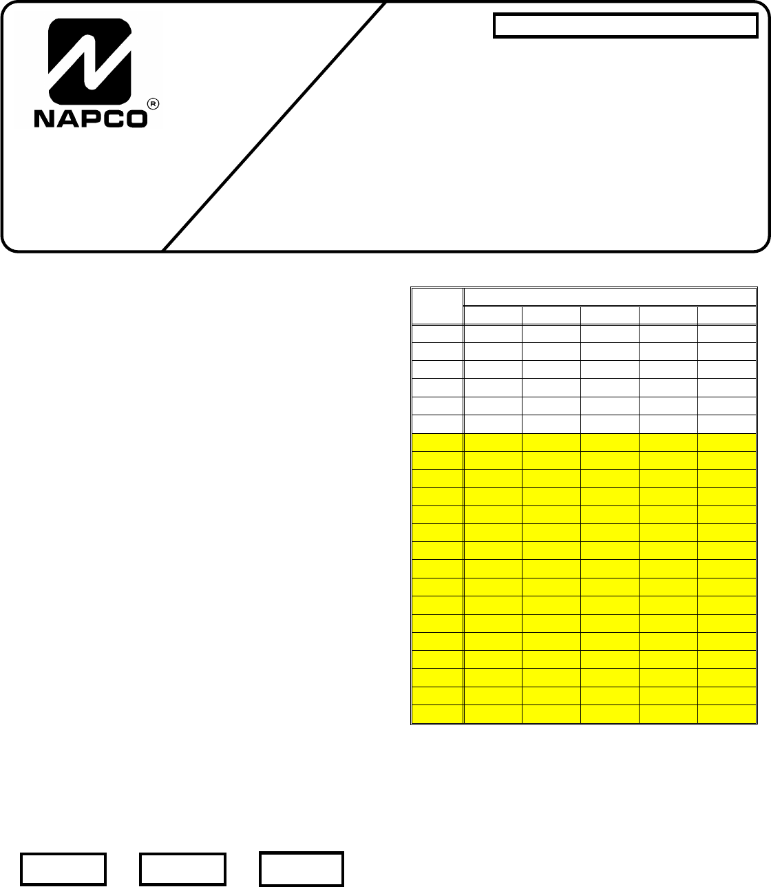
BaseBase
AddressAddress
Address JumpersAddress Jumpers
JP5JP5 JP4JP4 JP3JP3 JP2JP2 JP1JP1
1 ON ON ON ON OFF
2 ON ON ON OFF ON
3 ON ON ON OFF OFF
4 ON ON OFF ON ON
5 ON ON OFF ON OFF
6 ON ON OFF OFF ON
7 ON ON OFF OFF OFF
8 ON OFF ON ON ON
9 ON OFF ON ON OFF
10 ON OFF ON OFF ON
11 ON OFF ON OFF OFF
12 ON OFF OFF ON ON
13 ON OFF OFF ON OFF
14 ON OFF OFF OFF ON
15 ON OFF OFF OFF OFF
16 OFF ON ON ON ON
17 OFF ON ON ON OFF
18 OFF ON ON OFF ON
19 OFF ON ON OFF OFF
20 OFF ON OFF ON ON
21 OFF ON OFF ON OFF
22 OFF ON OFF OFF ON
Table 1. Jumper emplacement as a function of Base Address.Table 1. Jumper emplacement as a function of Base Address.
Shaded area is not applicable to GEM-P3200 or SS-P3200.Shaded area is not applicable to GEM-P3200 or SS-P3200.
PROGRAMMINGPROGRAMMING
The control panel must be programmed with regard to
the modules (4-zone or 8-zone) in use. Referring to the
respective Programming Workbook, program EZM TYPE to
enable the module. Starting in the first location and pro-
ceeding in succession, program a ‘‘1’’ for each 4-zone
group of expansion zones in the system. For example, if
one GEM-EZM8 is used for Zones 9 through 16 (two groups
of 4), program a ‘‘1’’ in the first and second locations (right
‘‘nibble’’). Similarly, if an GEM-EZM4 is used for Zones 17
through 20 (1 group), program a ‘‘1’’ in the third location
(right ‘‘nibble’’). Thus, each GEM-EZM4 will require a ‘‘1’’ in
only one location whereas each GEM-EZM8 will require a
GEM-EZM4, GEM-EZM8GEM-EZM4, GEM-EZM8
ZONE EXPANSION MODULESZONE EXPANSION MODULES
for MA3000, GEM-Series,for MA3000, GEM-Series,
Signature S5500 & SS-P SeriesSignature S5500 & SS-P Series
Control PanelsControl Panels
NAPCO SECURITY SYSTEMS, INC.
333 BAYVIEW AVENUE
AMITYVILLE, NEW YORK 11701
SALES, REPAIRS & TECHNICAL SERVICE
TOLL FREE: (800) 645-9445
TECHNICAL SERVICE DIRECT LINE
TOLL FREE: (800) 645-9440
INSTALLATION INSTRUCTIONS INSTALLATION INSTRUCTIONS
© Napco 1997 WI583C 2/97