


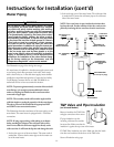
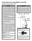
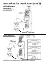
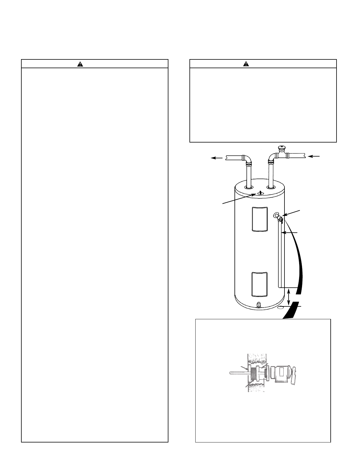
COLD
HOT
12
TEMPERATURE-
PRESSURE
RELIEF VALVE
FLOOR DRAIN
6″ AIR GAP
DISCHARGE PIPE
(Do not cap or plug)
CONDUIT
HOT
COLD
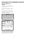
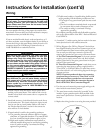
WARNING “RELIEF VALVE OPENING”
This water heater is provided with a combination Temperature-Pressure Relief Valve listed as complying with
the standard for Relief Valves and Automatic Gas Shutoff Devices for Hot Water Supply Systems, ANS Z21.22
and the code requirements of ASME.
Your local jurisdictional authority, while mandating the use of a Temperature-Pressure Relief Valve complying
with ANS Z21.22 and ASME, may require a valve model different from the one furnished with the water heater.
Compliance with such local requirements must be satisfied by the installer or end user of the water heater with
a locally prescribed Temperature-Pressure Relief Valve installed in the designated opening in the water
heater.
“Install Temperature-Pressure protective equipment required by local codes, but not less than a combina-
tion Temperature-Pressure Relief Valve certified as meeting the requirements for Relief Valves and
Automatic Gas Shutoff Devices for Hot-Water Supply Systems, ANS Z21.22 by a nationally recognized test-
ing laboratory that maintains periodic inspection of production of listed equipment or materials. The valve
must be oriented, provided with tubing, or otherwise installed so that discharge can exit only within 6 inches
above, or at any distance below the structural floor, and cannot contact any live electrical part.”
For safe operation of the water heater, the Relief Valve must not be removed or plugged.
See manual heading - “Temperature-Pressure Relief Valve” for installation and maintenance of Relief
Valve, discharge pipe and other safety precautions.
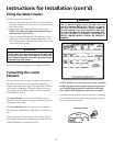
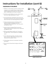
If a short shank (less than 2") temperature-pressure relief valve is to be installed
(as shown), a nipple and coupling must be used.
If a long shank (2" or longer) is to be installed, do not use the nipple and coupling.
●
●
TANK JACKET
BRASS
COUPLING
TANK
FITTING
TEMPERATURE-
PRESSURE
RELIEF VALVE
T&P RELIEF
VALVE PROBE
MUST EXTEND
INTO TANK
T&P
SHANK
LENGTH
(1
3
/
8
" x
3
/
4
")
BRASS
NIPPLE
Temperature-Pressure Relief Valve
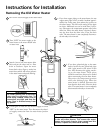
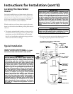
Instructions for Installation (cont’d)
WARNING
At the time of manufacture this water heater was provided
with a combination temperature-pressures relief valve cer-
tified by a nationally recognized testing laboratory that
maintains periodic inspection of production of listed equip-
ment or materials, as meeting the requirements for Relief
Valves and Automatic Gas Shutoff Devices for Hot Water
Supply Systems, and the current edition of ANSI Z21.22 •
CSA 4.4 and the code requirements of ASME. If replaced,
the valve must meet the requirements of local codes, but
not less than a combination temperature and pressure
relief valve certified as meeting the requirements for Relief
Valves and Automatic Gas Shutoff Devices for Hot Water
Supply Systems, ANSI Z21.22 • CSA 4.4 by a nationally rec-
ognized testing laboratory that maintains periodic inspec-
tion of production of listed equipment or materials.
The valve must be marked with a maximum set pressure
not to exceed the marked hydrostatic working pressure of
the water heater (150 lbs./sq. in.) and a discharge capacity
not less than the water heater input rate as shown on the
model rating plate. (Electric heaters - watts divided by
1000 x 3412 equal BTU/Hr. rate.)
Your local jurisdictional authority, while mandating the use
of a temperature-pressure relief valve complying with ANSI
Z21.22 • CSA 4.4 and ASME, may require a valve model dif-
ferent from the one furnished with the water heater.
Compliance with such local requirements must be satisfied
by the installer or end user of the water heater with a
locally prescribed temperature-pressure relief valve
installed in the designated opening in the water heater in
place of the factory furnished valve.
For safe operation of the water heater, the relief valve
must not be removed from it’s designated opening or
plugged.
The temperature-pressure relief valve must be installed
directly into the fitting of the water heater designated for
the relief valve. Position the valve downward and provide
tubing so that any discharge will exit only within 6 inches
above, or at any distance below the structural floor. Be cer-
tain that no contact is made with any live electrical part.
The discharge opening must not be blocked or reduced in
size under any circumstances. Excessive length, over 30
feet, or use of more than four elbows can cause restriction
and reduce the discharge capacity of the valve.
No valve or other obstruction is to be placed between the
relief valve and the tank. Do not connect tubing directly to
discharge drain unless a 6″ air gap is provided. To prevent
bodily injury, hazard to life, or property damage, the relief
valve must be allowed to discharge water in quantities
should circumstances demand. If the discharge pipe is not
connected to a drain or other suitable means, the water
flow may cause property damage.
The Discharge Pipe:
•Must not be smaller in size than the outlet pipe size of
the valve, or have any reducing couplings or other
restrictions.
• Must not be plugged or blocked.
•Must be of material listed for hot water distribution.
•Must be installed so as to allow complete drainage of
both the temperature-pressure relief valve, and the dis-
charge pipe.
• Must terminate at an adequate drain.
• Must not have any valve between the relief valve and
tank.
WARNING
The temperature-pressure relief valve must be manu-
ally operated at least once a year. Caution should be
taken to ensure that (1) no one is in front of or
around the outlet of the temperature-pressure relief
valve discharge line, and (2) the water manually dis-
charged will not cause any bodily injury or property
damage because the water may be extremely hot.
If after manually operating the valve, it fails to com-
pletely reset and continues to release water, immedi-
ately close the cold water inlet to the water heater,
follow the draining instructions, and replace the
temperature-pressure relief valve with a new one.