


© 2007 LUX PRODUCTS CORPORATION. ALL RIGHTS RESERVED
1
24 Volts A.C.
Electrical Rating: 24 to 30 Volts A.C.
Heat Anticipator: 0.20 to 1.2 Amp. Max.
Cool Anticipator: 0 to 1.0 Amp. Max.
SPECIFICATIONS
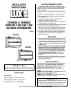
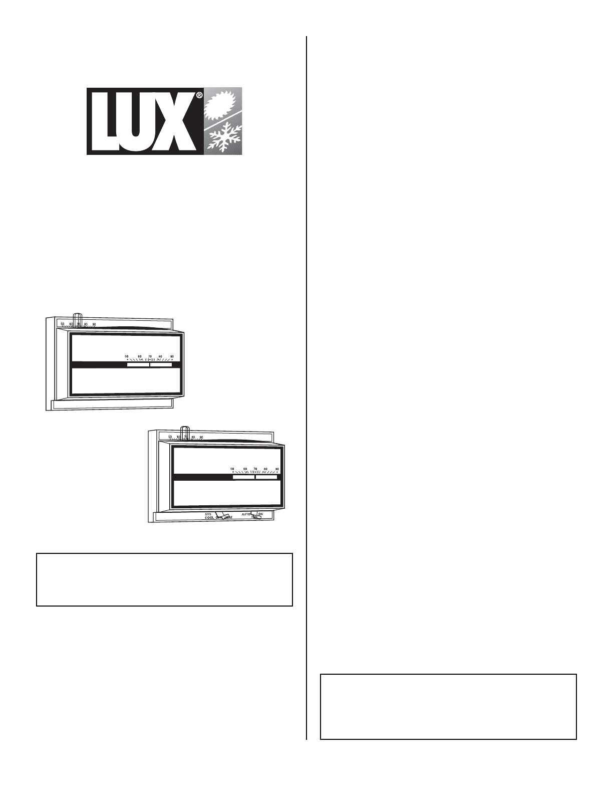
CH200SA & CH400SA
VERSATILE DELUXE LOW
VOLTAGE THERMOSTAT
INSTALLATION
INSTRUCTIONS
52010
LUX
LUX
CH400SA
CH200SA
WARNING
Not for use with compressors without time delays.
SELECTING THERMOSTAT LOCATION
The proper location of the room thermostat is most
important to insure that it will provide a comfortable home
temperature. Observe the following general rules when
selecting a location:
1. Locate it about 5 ft. above the floor with a free flow of
air.
2. Install it on a partitioning wall, not on an outside wall.
3. Never expose it to direct light or radiation from lamps,
sun, fireplaces, etc.
4. Avoid locations close to doors that lead outside,
windows, or adjoining outside walls.
5. Avoid locations close to radiators, warm air registers, or
in the direct path of heat from them.
6. Make sure there are no pipes or duct work in that part of
the wall chosen for the thermostat location.
7. Never locate it in a room that is warmer or cooler than
the rest of the home such as kitchen or hallway or on
the opposite side of the wall of a cold or unused room.
8. The living or dining room is normally a good location,
provided there is no cooking range or refrigerator on
opposite side of wall.
INSTALLATION
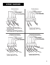
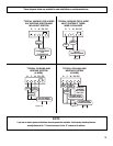
1. Remove cover from thermostat by pulling outward. Pull
thermostat wires through small holes beside terminal
screws on thermostat base and connect wires to proper
terminal screws per wiring diagrams. Note that on some
models wire leads may be connected to terminal screws
on back of base.
2. The thermostat can either be mounted to a standard
horizontal outlet box or mounted directly to the wall.
Place level on top of thermostat base and mark hole
locations for mounting screws.Push excess wire into
wall or switch box and plug up hole to prevent drafts
from affecting thermostat operation. Then attach
thermostat base loosely to wall with the two screws
provided.
3. Again place level on top of thermostat base to be sure it
is level. Then tighten mounting screws securely and
snap on thermostat cover.
HEATING ANTICIPATOR
The heating side of this thermostat is equipped with an
adjustable heater. Set heater indicator to match the
current rating of the primary control. The heater may be
adjusted for current ratings from .2 to 1.2 Amp.
Additional adjustments, if necessary, may be made as
follows:
BURNER CYCLES TOO LONG - Set adjustable heater to a
slightly lower dial setting (1/2 division).
BURNER CYCLES TOO SHORT - Set adjustable heater to a
slightly higher dial setting (1/2 division).
WARNING
The Adjustable Heater (Heat Anticipator) WILL BURN OUT if 25V
are applied directly to thermostat by shorting out the gas valve or
primary control during testing or by incorrect wiring.