


INSTRUCTION SHEET
12-01/Rev-02
ISF:302IC
WITH VAPOUR BARRIER COVER: NºVBE300 (Order separately)
1. Select a location for the fixture.
2. Fasten the edge of the
vapour barrier cover under the
wood joist. (Fig.1)
3. Install the fixture (see step A, B and C).
4. Install the ceiling vapour barrier. (Fig.1)
Note: Seal the edges of the vapour barrier cover and the
vapour barrier. (Fig.2)
FOR NEW CEILING:
A. MOUNTING BAR:
Note-1: The mounting bars are extensible from 12½" to 29" max.
Note-2: For off-centre installation, use 20" expandable mounting bars
(Nº1964, order separately).
1. Insert the mounting bars into the proper openings on the short side or the
long side of the
mounting frame. (Fig.4)
2. Align the
mounting bar with the bottom edge of the joist. (Fig.3)
3. Push in the
built-in nailer. (Fig.3)
B. MOUNTING FRAME:
1. Install the
locking clip. (Fig.5)
Note-1: The locking clip is also available separately
(Nº0098, order separately).
Note-2: To lock more securely into place fold the locking tabs. (Fig.4)
C. WIRE-IN:
1. Remove the appropriate "
Pry-out plug".
2. Insert the supply lead into the
junction box:
a) If using
FLEXIBLE CONDUIT: Use a BX connector (not provided).
b) If using
FLEX WIRE: Insert under the wire connector. (Fig.6)
3. Connect the
ground lead. (Fig.7,8)
4. Connect the
white leads (NEUTRAL) together, and the black leads
(120V) together. (Fig.7.8)
D. CEILING:
1. Cut a hole in the ceiling (3-3/4 for Model 302 or 4-3/4 for
Model 402), using the mounting frame as a template (if applicable).
(Fig.9)
2. Use the
screws to adjust the housing height. Note: Ensure
that the housing is level with the ceiling. (Fig.10)
3. Tighten the screws when completed. (Fig.10)
CAUTION: The lampholder must not be used for temporary lighting,
a protective glass is required for the lamp.
E.
TRIM:
Install the trim using the appropriate sheet.
F. TRANSFORMER / REPLACEMENT:
Note: Before performing maintenance on the transformer, make sure that the
electrical supply to the fixture is turned off.
1. Remove the housing and the two screws located inside. (Fig.10)
2. Push down on the spring
tab and release the plate. (Fig.11, 12)
3. Remove the plate from the ceiling, disconnect the wiring , and change the
transformer. (Fig.12)
4. Complete the connections following the wiring diagram (fig.7). Reinstall the
plate onto the spring. (Fig.12)
5. Replace the
housing into position. (Fig.10)
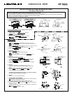
INSTALLATION INSTRUCTIONS FOR MOUNTING FRAME
FOR INSULATED CEILING
FIG.3 FIG.4
FIG.5
FIG.6
MOUNTING
FRAME
MOUNTING
BAR
LOCKING
TABS
MOUNTING
BAR
LOCKING
CLIP
MOUNTING
FRAME
"PRY-OUT"
PLUG
FLEXIBLE
WIRE
WIRE
CONNECTOR
JUNCTION
BOX
WOOD JOIST
FIG.1 FIG.2
VAPOUR
BARRIER EXTENDER
VAPOUR BARRIER
VAPOUR BARRIER
EXTENDER
VAPOUR BARRIER
SILICONE
SEALER
OR OTHER
FIXTURE
FIG.7
(MR)
INPUT(120V)
NEUTRAL (white)
GROUND
THERMAL
PROTECTOR
LAMP
LOW VOLTAGE
TANSFORMER
JUNCTION
BOX
WHITE
BALCK
MOUNTING
BAR
BUILT-IN
NAILER
WOOD
JOIST
FIG.9
FIG.10
HOUSING
THERMAL
PROTECTOR
LAMP
INPUT(120V)
NEUTRAL (white)
GROUND
WHITE
BLACK
JUNCTION
BOX
FIG.8
(ES)
302ESIC
302MRIC / 402MRIC
READ AND UNDERSTAND THESE INSTRUCTIONS BEFORE INSTALLING FIXTURE
This fixture is intended for installation in accordance with National Electrical Code or Canadian Electrical
Code (as applicable) and local regulations. To ensure full compliance with local codes and regulations, check with your local electrical inspector before
installation. To prevent electrical shock, turn off electricity at fuse box before proceeding.
Retain these instructions for maintenance reference.
SCREWS
FIG.11
FIG.12
TAB
PLATE
SPRING