


,
T
READAND UNDERSTAND THESE INSTRUCTIONS BEFORE INSTALLING FIXTURE INSTRUCTION SHEET NO.
“hisfixture isintended
for installation in accordance with the National Electrical Code and local regulations.
“o assure full compliance with local codes and regulations, check with your local electrical inspector before
wtallation. To prevent electrical shock, turn off electricity at fuse box before proceeding.
IS:9147
Retain these instructions for maintenance reference.
0395
Page 1 of 1
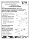
SURFACEFEEDCONNECTOR
FORUSEWITH PROFILETRACKSYSTEM ONLY
WARNING:
● TURN OFF POWER AT FUSE BOX BEFORE INSTALLING ELECTRICAL CONNECTOR AND TRACK.
● DO NOT USE ELECTRICAL CONNECTOR AS A CONDUIT SUPPORT. INDEPENDENT CONDUIT SUPPORTS (SUCH AS
CONDUIT STRAPS) MUST BE USED TO ATTACH THE CONDUIT INSTALLATION TO THE BUILDING STRUCTURE.
. OBSERVE POLARITY; WHITE NEUTRAL WIRE MUST BE CONNECTED TO THE TERMINAL MARKED “NEUT” IN THE
ELECTRICAL CONNECTOR.
. USE 12 GA. OR 14 GA. SOLID WIRE IN ELECTRICAL CONNECTOR ONLY.
A.
INSTALLING SURFkCE FEED CONNECTOR.
.
—
~/; —
/,/
j,
1.Point the POLARITY TAB away from the BEAD ON the track.
,,,
\\\ ‘
2, Insert SURFACE FEED CONNECTOR into track. Ensure CONTACT
b<!—.~
—
BLADES insert
into the GAP of the TRACK COPPER CONDUCTOR.
3. Tighten LOCKING SCREW.
(BYOTHERS)
CONTACT BLAOE
B. DIRECT POWER FEED USING SURFACE CONDUIT.
THROUGH CE!LING FEEO
1.
Remove BO~OM COVER by removing SCREW (retain).
Lg
2. Remove PLASTIC TAB from BOTTOM COVER.
~
3. Screw the ELECTRICAL FITTING into the METAL PI-ATE of the
SURFACE FEEOI
Surface Feed Connector.
4. Pass Supply LEAOS through ELECTRICAL FITTING and secure
conduit to ELECTRICAL FITTING.
5. Strip and form Supply LEADS to fit into SURFACE FEED
CONNECTOR. Fasten Supply LEADS to SCREW TERMINALS;
NEUTRAL (WHITE) LEAD to terminal marked “NEUT”. GROUND
LEAD to TERMINAL marked “GND”. HOT (BLACK) LEAD to
BRASS SCREW.
6. Fasten BOTTOM COVER to SURFACE FEED CONNECTOR using SCREW.
~
C.
DIRECT POWER FEED FROM ABOVE CEILING
-
NEUTRAL SUPPLY
,.
TRACK
1.
Remove BOTTOM COVER by removing SCREW (retain).
BEAO
! WIRE (WHITEi
~ LOCKINGSCREW ~
2. Remove Knock Out from METAL PLATE.
\
3. Secure ELECTRICAL FITTING TO MEAL PLATE using the NUT
/
provided.
,,———— ——
L
“- ~~d=.. “ —.
(c b, —-— .:
NOTE: Special care must be taken when making the
,(3T f—.— -- -—
hole in the mounting surface to prevent the hole from
(~:~p:-- ‘~~--
-F”--- ~
being visible when the track is mounted. The screws
-~’/---.-=>._-, ::$~ “–-
on the ELECTRICAL FllllNG may have to be cut to
conceal the mounting hole.
,’––-. .—.
/
~.–
w—--- ~—z::
4.
Follow instruction 4, 5 and 6 above.
—HOT SUPPLYWIRE
- SUPPLYWIRE(BLACK)
- POLARllYTAB
D. POWER FEED FROM STEM KIT
GROUNO
c
?,
—–- 7/16STRIP
1.
Remove BOTTOM COVER by removing SCREW.
>,
p
~;”,
SUPPLYWIRE
2. Remove KNOCK OUT from the TOP METAL PLATE.
-.
YCH
~ — ________ --
3. Pass SUPPLY LEADS through KNOCK OUT HOLE.
/ --.-——–––-
4. Follow instructions 5 and 6 above.
‘lWOWIRES MAY BEATTACHEO
I
@
FALL RIVER MASSACHUSETTS, 02720
l-I c> 1+ ~c>lm I 1= 1? MON::::::;EC, CANADA