


INSTALLATION INSTRUCTIONS
1
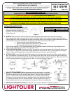
PREPARATION: Cut appropriately sized
hole in ceiling at the position desired using
the aperture sticker provided as a
template. Cut to the outside edge of the
sticker (Figure A).
Figure A
APERTURE HOLE SIZE
1101FR SERIES 7-1/8” (181mm) DIA.
1001FR SERIES 5-1/2” (140mm) DIA.
2
WIRE-IN: Wire-in and push J-Box through ceiling opening before attaching Mounting Ring (see note below).
Open appropriately sized and positioned knock out in the J-Box based on your supply wire style and feed direction.
Secure feed wire to J-Box in accordance with local and national codes. Wire luminaire to supply leads using wire nuts
(local hardware item). Place all electrical connections in the J-Box and close the J-Box cover.
• White Luminaire Lead to Neutral Supply Lead
• Black Luminaire Lead to Hot (120v or 277v) Supply Lead
• Bare Luminaire Lead to Ground Supply Lead
NOTE: When installing 1101FR Series Remodeler Kits it is possible to attach the Mounting Ring (see below) first,
then hang the J-Box temporarily from the ring to assist wire-in.
3
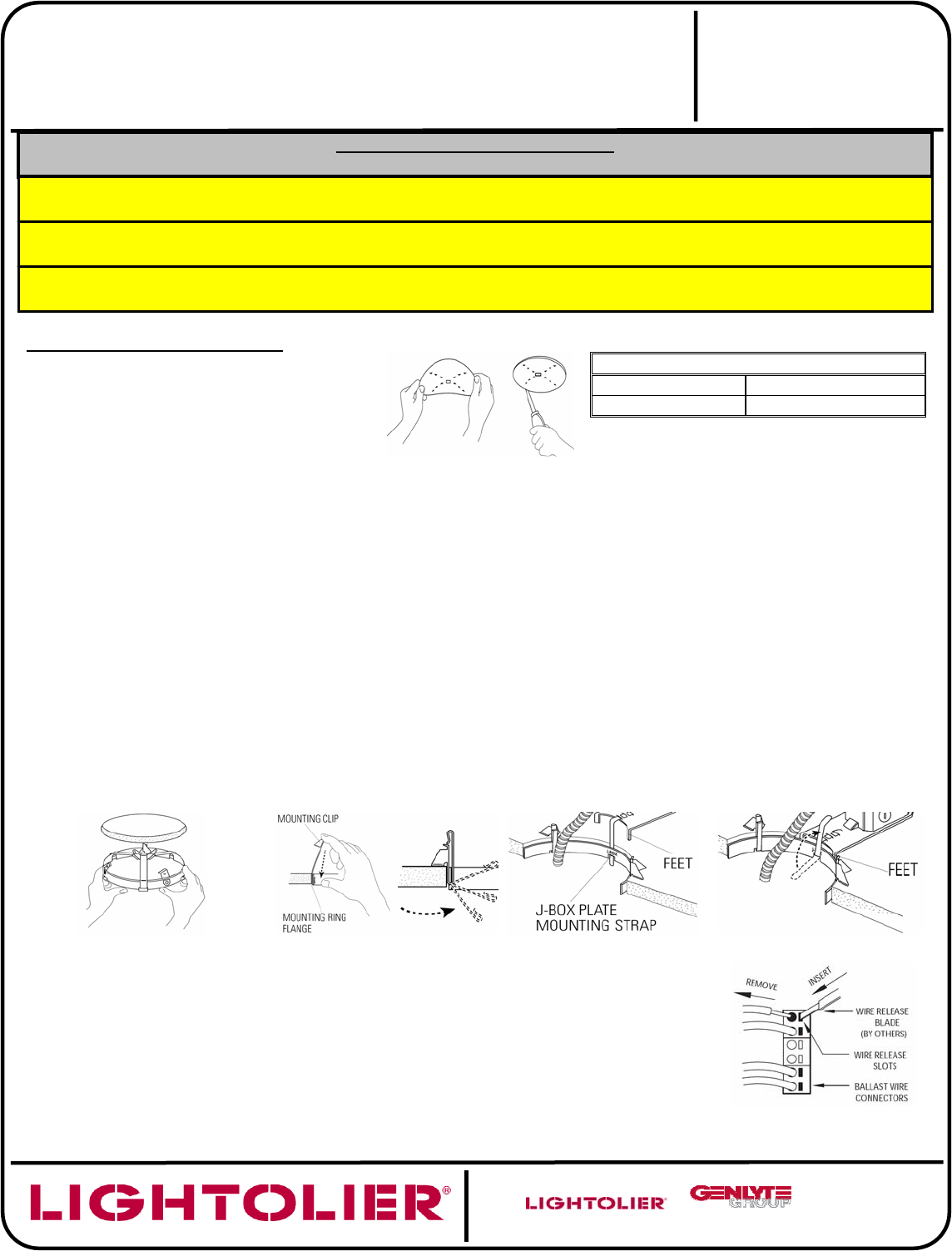
ATTACH MOUNTING RING: Push Mounting Ring into opening until flange sits against ceiling (Figure B) making sure
“J-Box” Slot is in a position that will ensure enough space above ceiling for the “J-Box” to sit flat against ceiling (see
step 4). Slide mounting straps down to trap ceiling thickness, then bend up to secure (Figure C).
4
ATTACH J-BOX: Insert J-Box Mounting Strap between the ceiling material and the Mounting Ring and through the “J-
Box” Slot identified on the Mounting Ring. Pull the Strap until the J-Box Plate sits flat on the ceiling with the feet over
the edge of the ceiling thickness (Figure D). Bend the J-Box Mounting Strap upwards to secure. Make sure the J-Box
Plate is securely attached to the ceiling and the J-Box is in the position shown (Figure E).
Figure B
Figure C
Figure D
Figure E
*
BALLAST REPLACEMENT: Ballast replacement must be performed by a “qualified
electrician”. TURN OFF POWER. Remove reflector trim from luminaire. Remove the J-
Box from the Mounting Ring by reversing step 4 above. Pass the J-Box through the
aperture. Remove J-Box cover to which the ballast is mounted by lifting the spring.
Disconnect all input wiring to the ballast. Release all wires from ballast wire connectors
by inserting small blade tool, with insulated handle, into wire release slots (Figure F).
Remove ballast from j-box door and replace with new ballast. Rewire and reassemble.
Figure F
*
REFLECTOR TRIM INSTALLATION: See separate Trim Instruction Sheet for installation procedure.
A COMPANY
631 Airport Road, Fall River, MA 02720
READ AND UNDERSTAND THESE INSTRUCTIONS
BEFORE INSTALLING LUMINAIRE.
This luminaire is intended for installation in accordance with the National Electrical Code and local regulations.
To assure full compliance with local codes and regulations, check with your local electrical inspector before
installation. To prevent electric shock, turn off electricity at main power supply before proceeding.
Retain these instructions for maintenance reference.
INSTRUCTION SHEET NO.
IS:1101FR
Page 1 of 1
A1106
INSTALLATION PROCEDURE FOR:
L
y
tecaster
®
1101FR and 1001FR Series Remodeler Frame-In Kits
CAUTION: (RISK OF FIRE) THIS IS A NON-IC RATED FRAME-IN KIT.
DO NOT INSTALL INSULATION ABOVE OR WITHIN 3 INCHES (76mm) OF ANY PART OF LUMINAIRE.
CAUTION: USE ONLY WITH REFLECTOR TRIMS PROVIDED BY LIGHTOLIER. USE OF OTHER MANUFACTURER’S TRIMS
MAY VOID THE UNDERWRITERS LABORATORIES LISTING AND COULD CONSTITUTE A FIRE HAZARD.
CAUTION: BEFORE INSTALLING FRAME-IN KIT AND REFLECTOR TRIM, READ ALL MARKINGS ON FRAME-IN KIT AND
REFLECTOR TO DETERMINE LAMP WATTAGE AND TYPE APPLICABLE FOR YOUR INSTALLATION.