


READ AND UNDERSTAND THESE INSTRUCTIONS BEFORE INSTALLING FIXTURE
This fixture is intended for installation in accordance with the National Electrical Code and local regulations.
To assure full compliance with local codes and regulations, check with your local electrical inspector before
installation. To prevent electrical shock, turn off electricity at fuse box before proceeding.
Retain these instructions for maintenance reference.
LIGHTOLIER a GENLYTE company.
631 Airport Road, Fall River, MA 02720
®
INSTRUCTION SHEET NO.
IS:1078
A0997 Page 1 of 1
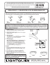
INSTALLATION OF 7•11 REFLECTOR TRIM IN THE 1000 SERIES FRAME-IN KITS
1. FRAME-IN (Fig. A)
See Frame-In Kit Instruction Sheet for installation procedure.
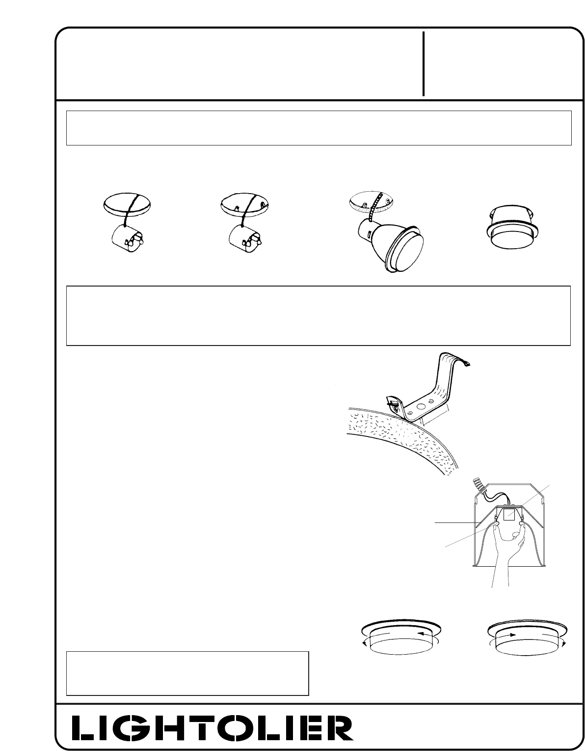
2. ROTATE ROTO-CLIPS (Fig. B)
(if Frame-In Kit is so equipped)
As shown in Fig. E
3. SNAP-ON (Fig. C)
Insert SOCKET CUP in neck of REFLECTOR. Make sure SPRINGS
of SOCKET CUP snap into SLOTS of REFLECTOR.
4. PUSH UP (Fig. D)
Push REFLECTOR TRIM straight up until it is tight against ceiling.
Note: To remove REFLECTOR TRIM turn REFLECTOR TRIM
counterclockwise while pulling downward. When using 1004
Series Frame-In Kits, squeeze REFLECTOR SPRING from inside
until the TRIM disengages. To retrieve SOCKET CUP, pull on one
of the SOCKET SPRING legs to disengage. (Fig. F)
TO LAMP
1. After pushing REFLECTOR TRIM tight against ceiling, twist Lexan
DIFFUSER counterclockwise until DIFFUSER disengages, the pull
down. (Fig. G)
2. Install proper size lamp as indicated inside the REFLECTOR.
3. Replace DIFFUSER. Line up the SLOTS on DIFFUSER with the
BUMPS on the REFLECTOR, push up and twist clockwise until the
diffuser engages. (Fig. H)
WARNING: BEFORE INSTALLING REFLECTOR TO FRAME-IN KIT, READ MARKINGS IN REFLECTOR TRIM AND IN SOCKET CUP
OF FRAME-IN KIT TO DETERMINE LAMP WATTAGE AND TYPE APPLICABLE FOR YOUR INSTALLATION. IF I.C. TYPE FRAMING
KIT IS USED, IT MAY BE INSTALLED IN DIRECT CONTACT WITH INSULATED CEILING. IF A NON I.C. TYPE FRAME-IN KIT IS USED,
DO NOT INSTALL INSULATION WITHIN 3 INCHES OF FIXTURE SIDES OR WIRING COMPARTMENT, NOR ABOVE FIXTURE IN
SUCH A MANNER TO ENTRAP HEAT.
Fig. C
SNAP-ON
Fig. D
PUSH-UP
Fig. A
FRAME-IN
Fig. B
ROTATE CLIPS
NOTE: Use this Instruction Sheet only when Lytecaster Trim is being installed in the 1000 series Frame-In Kits. If not, disregard
this Instruction Sheet. It is recommended you maintain a copy of the following instructions for reference.
Fig. E
ROTO-CLIP
POSITION
Fig. F
REFLECTOR
SPRING
SOCKET SPRING
LEG
SOCKET
CUP
Fig. G Fig. H
TO OPEN
TO CLOSE
WARNING: USE ONLY REFLECTOR TRIMS PROVIDED BY
LIGHTOLIER INC. USE OF OTHER MANUFACTURERS’ REFLECTOR
TRIMS VOIDS THE UNDERWRITERS LABORATORIES LISTING
AND COULD CONSTITUTE A FIRE HAZARD.