


/
INSTRUCTIONSHEETNQ. =
;,.,
“‘
INSTRUCTIONS FOR ASSEMBLY AND INSTALLATION
IS:4100AZ
0790
Page 1 of 2
READ AND UNDERSTAND THESE INSTRUCTIONS BEFORE INSTALLING FIXTURE.
This fixture is intended for installation in accordance with the National Electrical Code and local regulations.
To assure full compliance with local codes and regulations, check with your local electrical inspector before
installation. To prevent electrical shock, turn off electricity at fuse box before proceeding,
Retain these instruction for maintenance referenca.
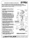
1. Thread MOUNTING”” SCREWS into CROSSBAR and
attach CROSSBAR to OUTLET BOX with OUTLET
BOX SCRSWS.
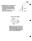
2. Aseemble CABLES to ADJUSTING COLLARS (see
page 2 for procedure). Thread ADJUSTING COLLARS
(attached to CABLES) onto ADJUSTING SCREWS
(attached to’ CANOPY).
3. Pueh CABLE (attached to HUSK), through STRAIN
RELIEF BUSHING end shorten CABLE to
appropriate @n th to match the distance of the
1“
fixturs from cei mg. Bring partial assembly to ceiling,
and make connections Black fixture lead or fixturs
lead without tra~er mark to black eupply Iea& white
‘fixture lead or fixture lead with tracer mark to white
eupply lead. Use WIRE NUTS (local hardware item).
Place connections in OUTLET BOX. Uninsulated wire
is for grounding and must be attachad to ground
wi~ or grounding terminal in OUTLET BOX.
,
4. Pla& CANOPY over MOUNTING SCREWS and
secure against ceiling with CAP SCREWS.
MUTION Overtightening can damage CANOPY
WIRE
NUTS
CANOPY
---u”
CAP SCREWS-
CABLE
HUSK=
GROUND LEAD
7 (UNINSULATED)
5. Level partial eeeembly by turnin ADJUSTING
t
&
DIFFUSER (STACKEDGL4SS
COLLA,~S on CANOPY Adjuet ORD to appropriate F0R~&~~~!&~4~$~eLE
length, push, excees through STRAIN RELIEF
REFER TO STACKEDGLASS
BUSHING and into OUTLET BOX. Secure CORD by
ASSY.DETAIL ON PAGE2.
\,
driving SST SCREW against cord.
6. Diagonally tilt UPPER DIFFUSER (stacked glees for
fixture 4100, marble for fixture 4102) and fit it over 3
BOSSES on LOWER CASTING. Center DIFFUSER so
~
it rests securely on BOSSES.
.,,
5’
7
\
SET SCREW
7. Lamp with IOOW Max., clear Tungsten Halogen T4,
mini-canbaee lamp. Follow lamp menufacturs.t’e
lampin~ :recommendations and grasp lamp with
clean beeue to ‘avoid, fingerprints (grease) which may
affect- Iarnp life.
8. After un’ acti”ng@W’ER GLASS ASSEMBLY, loosen
& ““TWIST-” CK KNOBS ‘three comDlete turns.
,9. Ineert GLASS’ CYLINDER into LOWER GIASS
ASSEMBkY so flange on GLASS CYLINDER rests
evenly on UPPER GIASS DISK
10. Install LOWER GLASS ASSEMBLY by inserting three
TWIST-LOCK .KNOBS attached to assembly into the
KEYSLOTS in U)WER CASTING. Rotate assembly
until it fully engages in the KEYSLOTS.
.
SOSSES ~
a \“wERcAsT’N(
GMS CVLIN
UPPEJ5~LASS
~
CAUTION: MAXIUM WAlTAGE MARKED ON
FIXTURE MUST NOT BE EXCEEDED.