


24
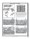
NOTE: DIAGRAMS & ILLUSTRATIONS ARE NOT TO SCALE.
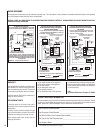
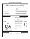
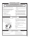
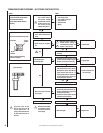
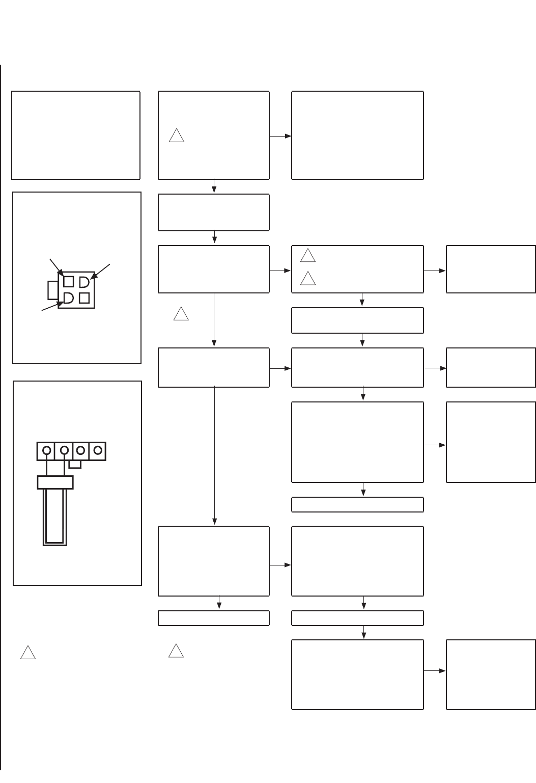
START CHECK
• Turn Off Gas Supply.
• Ensure Valve Switch Is In ON Position.
• Disconnect Control Harness.
• Turn On Optional Remote Switch (if
applicable)
• Check for proper volt-
age at control harness
(see insert A). Voltage
should be 24V between
remote switch or pres-
sure switch and 24V
common and 24V hot.
NO
• Line voltage power
• Low voltage transformer
• Limit controller
• Remote Switch
• Wiring
YES
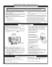
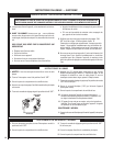
• Plug control harness into
valve. Wait for internal check
delay.
• Igniter warms up and glows
red.
NO
• With pilot burner cable con-
nected, measure voltage at
valve HSI element output. 24V
nominal. (See insert B)
NO
• Replace valve.
YES
YES • Replace igniter/fl ame rod
assembly.
YES
• Turn on gas supply.
• Pilot burner lights.
NO
• Check that pilot gas is fl owing. Wait
to ensure pilot gas tubing is purged.
Recycle call for heat if necessary.
NO
• Replace valve.
YES
YES
• Measure voltage between 24V hot and
24V common leads to valve control.
Must measure at least 19.5 VAC with
igniter powered (see insert A). To
identify proper lead, this check must
be done with the valve control con-
nected and igniter powered.
NO
• Check transformer and
line volt supply.
YES
• Replace Pilot Assembly.
• Main valve opens and main
burner lights.
NO
• Check that pilot fl ame makes good
contact with pilot burner fl ame rod.
• Check for good electrical connection
through the pilot tubing.
• If both of the above are good, replace
igniter/fl ame rod assembly.
YES YES
• System Is okay. • Cycle thermostat off and back on.
Igniter will cycle off and
back on once during the 90
second ignition trial. All
voltage measurements must
be taken while the igniter is
powered.
When measuring voltage
at connections, use care
to ensure terminals are
not damaged.
• Main burner lights.
NO
• Replace valve.
Insert A
End View of Control Harness Connector
24 Volt
Common
24 Volt Hot
24 Volt
Switched
Check For Damaged or Missing
Terminals in Connector
Insert B
Igniter Terminals
1
2
2
1
2
1
TROUBLESHOOTING PROCEDURE - ELECTRONIC IGNITION SYSTEM