


NOTE: DIAGRAMS & ILLUSTRATIONS NOT TO SCALE.
11
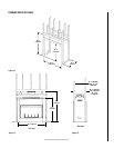
Using a FTF13-CTDT Chase Termination:
Refer to specific installation instructions in-
cluded with the FTF13-CTDT chase termination
for clearance and installation details.
Using a FTF13-CT1 Chase Termination:
Refer to specific installation instructions in-
cluded with FTF13-CT1 chase terminations for
clearance and installation details.
Using a FTF13-CT2 Chase Termination:
Refer to specific installation instructions in-
cluded with FTF13-CT2 chase terminations for
clearance and installation details.
Note: It is recommended that all exterior ex-
posed metal fireplace components; such as ter-
minations, flashings, storm collars and/or flue
be painted with a premium quality, high tem-
perature, rust preventative paint designed for
metal. This is especially important when instal-
lations are made in abnormally adverse or corro-
sive environments; such as near lakes, oceans or
in areas with consistently high humidity condi-
tions. Consult the paint manufacturers instruc-
tions for proper preparation and application.
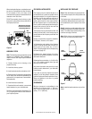
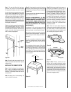
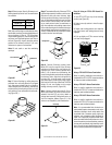
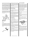
Next, slide roof flashing over extended chimney
section that previously has been installed above
the roof opening in Step 4. FTF10 flashings
require flashing spacers. Slide flashling all the
way down until the flashing base rests flat on
the roof (
Figure 28
). Again, check the vertical
position of the chimney and the 2" (51 mm)
minimum air space to combustibles.
Note: Do not caulk or seal the ventilating
openings.
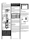
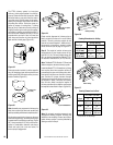
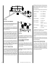
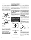
Figure 30
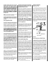
Step 9. Security Chimneys locking band,
Model FLB, may be required if the chimney
extends too high above the roof flashing. As
a general rule, if the chimney extends more
than 6' (1.8 m) above the roof/flashing, the
use of locking bands is advisable to strengthen
the chimney joints. Align the locking band at
the pipe joint. Locking bands wrap around
pipe joints equally covering the joints of both
pipe sections. Use nut provided and TIGHTEN
snugly. Do not over tighten as this might
damage chimney section (
Figure 30
).
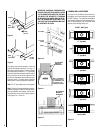
Note: If chimney extends more than 8' (2.4 m)
above roof surface, guy wires are also recom-
mended. Use three (3) guy wires, attach to
locking band assembly, extend and secure to
roof in a triangular pattern (Figure 31 ). Guy
wires are not supplied by the manufacturer.
Step 7. Secure flashing by nailing along the
perimeter into roof using 8d nails. If shingled
roof, slide upper end and sides of roof flashing
under shingles (trim if necessary), seal the top
and both sides of the flashing to the roof with
roof caulking. Cover nail heads with roof caulk-
ing (
Figure 29
).
Figure 29
Step 8. The standard Security Chimneys FTF10
roof flashing assembly includes a storm collar.
Slide storm collar over outer chimney, align
with top surface of flashing, insert storm tab in
slot, pull tight and bend tab back over slot. Seal
storm collar to outer chimney with roof caulk-
ing or mastic around entire circumference of
pipe. Also add extra roof caulking where storm
collar meets flashing and to the tab/slot area to
seal completely against water penetration (
Fig-
ure 30
). Check all joints very carefully to ensure
no water intrusion can take place.
Figure 28
Mastic
Locking Band
Roof Ridge
120°
FTF13 Chimney
FTF10 Flashing
Do Not Seal
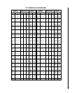
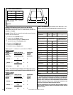
Step 6. Select proper Security Chimneys roof
flashing based on pitch of roof. Use chart below
for selection:
Roof Pitch FTF10
Flat to 6/12 F10-F6
6/12 to 12/12 F10-F12
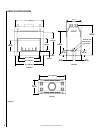
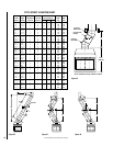
Figure 32
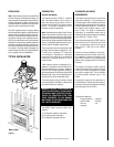
Step 10. Using an FTF13-CTD Round Ter-
mination:
1. Hold FTF13-CTD over top of last chimney
section (
see Figure 32
).
2. Center inner slip section in inner flue pipe-
slip down.
3. Center outer locking section over outer flue
pipe. Push down until locking tabs are firmly
engaged.
4. Pull up slightly on CTD to ensure locking
joint has firmly engaged.
Figure 31
20"
(508mm)