


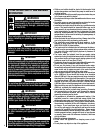
Retaining clip
Burner
(Manifold)
Pressure
Regulator
Pressure
Setting
Turn on gas supply and test for gas leaks using a gas leak test
solution (also referred to as bubble leak solution).
NOTE: using a soapy water solution (50% dish soap, 50% water)
is an effective leak test solution, but it is not recommended,
because the soap residue that is left on the pipes/fittings can
result in corrosion over time.
A. Light the appliance (refer to the lighting instructions label in
the control compartment or on Page 13).
B. Brush all joints and connections with the gas leak test
solution to check for leaks. If bubbles are formed, or gas
odor is detected, turn the gas control knob (off/pilot/on)
to the “OFF” position. Either tighten or refasten the leaking
connection, then retest as described above.
C. When the gas lines are tested and leak free, be sure to rinse
off the leak testing solution.
D. Observe the individual tongues of flame on the burner. Make
sure all ports are open and producing flame evenly across the
burner. If any ports are blocked, or partially blocked, clean out
the ports.
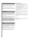
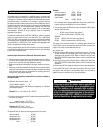
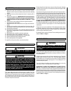
The heater regulator controls the burner pressure which should
be checked at the pressure test points located on the control
valve itself (shown in Figure 8) for burner (manifold) and
regulator setting pressure.
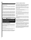
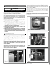
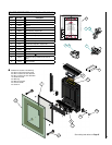
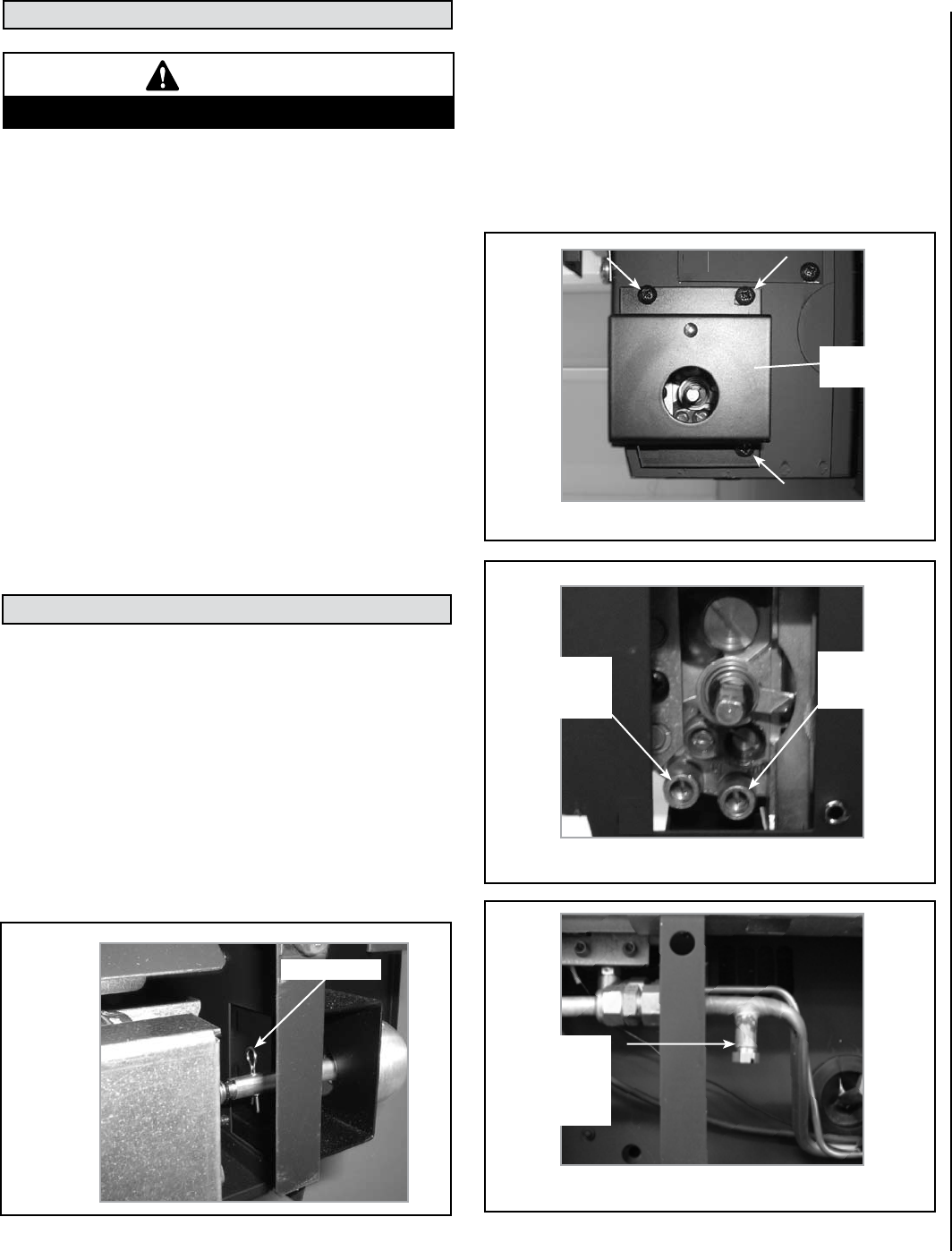
The pressure test points are located on the gas valve. To access
the valve and the test points, firstly remove the control knob
spindle from the valve spindle by removing the retaining clip
shown in Figure 6.
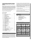
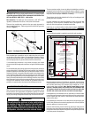
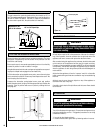
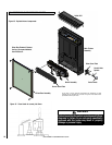
Withdraw the control knob and spindle from the heater and next,
remove the gas valve cover plate by first removing the three
retaining screws indicated in Figure 7.
14.0 CHECKING THE GAS CONNECTIONS
15.0 GAS PRESSURE CHECK
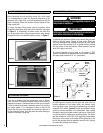
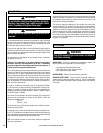
The pressure test points are located as shown in Figure 8. An alternative
burner (manifold test) point is located below the left hand side of the
burner as shown in Figure 9.
The pressure regulator on manual models is preset and locked to avoid
tampering. If the pressure is not as specified in Table 1 on Page 3,
replace the regulator with P/N H6063 for Natural Gas units and H7001
for Propane Gas units.
Replace the test point screws after pressure measurement ensuring no
gas leaks. All instructions must be left in the possession of the user
for safekeeping.
9
Alternative
Burner
Manifold
Test Point
Gas Valve
Cover Plate
NOTE: DIAGRAMS & ILLUSTRATIONS ARE NOT TO SCALE
WARNING
Never use an open flame to check for leaks.
Figure 6
Figure 7 - Valve Cover Retaining Screws
Figure 8
Figure 9