


HEAT PUMP KITS AND ACCESSORIES
©1993 LennoxIndustries Inc.
502,673M
Dallas,Texas 9/93
Supersedes 3/92
Litho U,S,A.
SOLID STATE DEFROST
REPLACEMENT BOARD
INSTALLATION INSTRUCTIONS FOR SOLID STATE DEFROST REPLACEMENT BOARD
LB-83114C (61H42) USED ON HP7-1, -2, HP8, CliP9 AND CliP10 SERIES UNITS
,/SHIPPINGANDPACKING _ : : :: : ]
Package 1 of 1 contains:
1- Control board on mounting bracket
1- Defrost thermostat
1- Outdoor fan/defrost relay
8- Wires with 3/16" terminals
1- Screw
2- Wire nuts
/tNSTA_TiON: :
1- Turn off power supply to unit.
2- Remove compressor access panel and control
box cover.
A- Defrost Thermostat
3- Disconnect coil thermistor from coil return bend
and air thermistor from fan section. Replace coil
thermistor with provided defrost thermostat.
Secure to liquid line as close as possible to the
outdoor coil.
NOTE-/t may be necessary to remove the front corner
panel for access to coil thermistor,
B-Defrost Board
4- Remove and retain screwfrom existing solid state
defrost board located in control box. Note
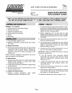
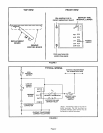
existing wiring. See figure 1.
5- Install newcontrol board assembly using existing
screw and hole.
6- Drill new hole into control panel and secure with
screw provided in kit.
C-Outdoor Fan/Defrost Relay
7- Remove outdoor fan/defrost relay. Install
replacement outdoor fan/defrost relay.
1- Connect one end of long wire (provided) to "HLD"
terminal on the defrost board. Disconnect defrost
high pressure switch from between high pressure
switch and loss of charge switch.
2-Splice remaining end of long wire to wire
between high pressure switch and toss of charge
switch where high pressure switch was originally
connected.
3- Connect onewire from defrost relaycoitto "OUT"
terminal of defrost board.
4- Cut off terminal of remaining wire from defrost
relay coil and strip wire 5/8 inch. At a convenient
location, splice wire to long wire from "HLD"
terminal using a wire nut.
5- Connect wire from defrost thermostat to one of
the "24V" terminals on defrost board.
IMPORTANT-Make sure defrost thermostat is securely
fastened to the fiquid line.
6- Cut off terminal from remaining defrost
thermostat wire and strip wire 5/8 inch. Splice
with one of the defrost pressure switch wires
using a wire nut.
7- Locate blue transformer wire and splice with
remaining defrost high pressure switch wire
using a wire nut.
8- Connect the remaining existing wire to "COM"
terminal on defrost board.
9- Defrost time interval can be selected to defrost
every 30, 60 or 90 minutes. This is selected using
the jumper on the defrost board.
10-Replace all panels and restore power to unit.
Page 1