


Page 1
®
E2003 Lennox Industries Inc.
Dallas, Texas, USA
OPERATION
MANUAL
Merit
R
Series Thermostat
The Lennox Merit
®
Series Thermostat 51M32 is a nonpro-
grammable electronic thermostat that is easy-to-use and
has a large, easy-to-read display and excellent tempera-
ture control. The thermostat also includes a programmable
filter change reminder and a system check indicator. The
system check indicator will notify the user of the need for
equipment service.
Thermostat 51M32 is suitable for non-heat pump, single−
stage heat/single cool applications that are matched with a
gas or electric furnace.
General
These instructions are intended as a general guide and do
not supersede local codes in any way. Consult authorities
having jurisdiction before installation.
Check equipment for shipping damage. If you find any
damage, immediately contact the last carrier.
Introduction
This document describes the operation of Lennox thermostat
51M32. Refer to the installation manual for instructions re-
garding installation and wiring of the thermostat.
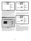
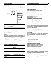
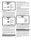
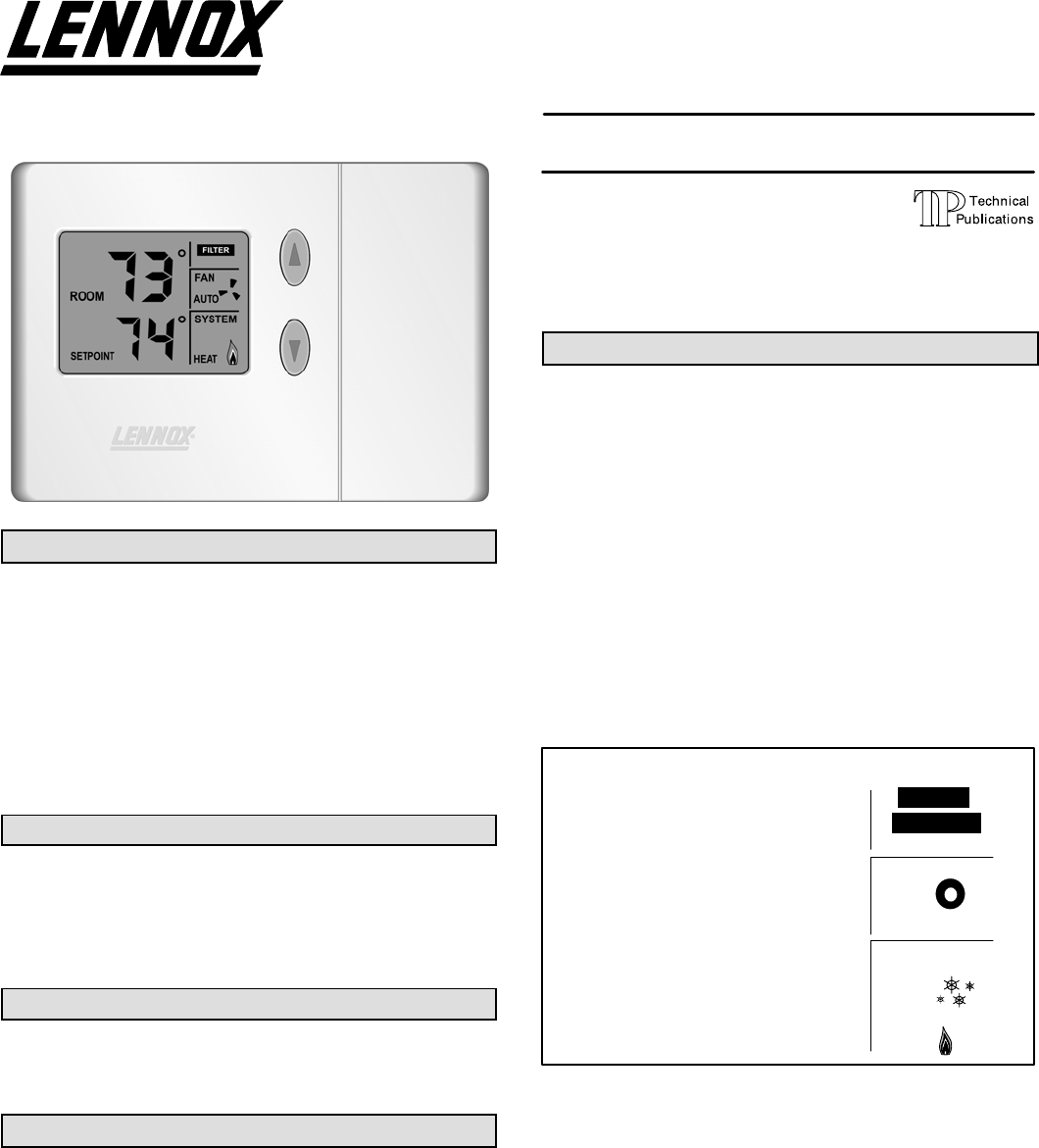
Initial Thermostat Power-up
When power is initially applied to the thermostat, the dis-
play will appear as shown in figure 1.
Litho U.S.A.
Merit
®
Series Thermostat
CONTROLS (51M32)
504,865M
09/04
RETAIN THESE INSTRUCTIONS
FOR FUTURE REFERENCE
Table of Contents
Merit
®
Series Thermostat 1. . . . . . . . . . . . . . . . . . . . . .
General 1. . . . . . . . . . . . . . . . . . . . . . . . . . . . . . . . . . . . . . .
Introduction 1. . . . . . . . . . . . . . . . . . . . . . . . . . . . . . . . . . . .
Initial Thermostat Power-up 1. . . . . . . . . . . . . . . . . . . . . .
Heating Control 2. . . . . . . . . . . . . . . . . . . . . . . . . . . . . . . .
Cooling Control 3. . . . . . . . . . . . . . . . . . . . . . . . . . . . . . . .
Adjusting Temperature Setpoint 3. . . . . . . . . . . . . . . . . .
Fan Control 4. . . . . . . . . . . . . . . . . . . . . . . . . . . . . . . . . . . .
Filter Reminder 4. . . . . . . . . . . . . . . . . . . . . . . . . . . . . . . .
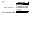
Service Indicator 5. . . . . . . . . . . . . . . . . . . . . . . . . . . . . . .
Thermostat Reset 5. . . . . . . . . . . . . . . . . . . . . . . . . . . . . .
Default Thermostat Settings 5. . . . . . . . . . . . . . . . . . . . .
Technical Specifications 5. . . . . . . . . . . . . . . . . . . . . . . . .
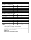
Thermostat Output Table 6. . . . . . . . . . . . . . . . . . . . . . . .
Display − Initial Power−Up
Figure 1
ROOM
SETPOINT
88
88
FILTER
SERVICE
FAN
ON
AUTO
SYSTEM
COOL
OFF
EMG.
HEAT
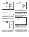
All display segments are momentarily activated. This oc-
curs as a normal part of thermostat initialization. Within a
few seconds, the display will appear as shown in figure 2
(figure shows temperature in Fahrenheit units).