


INSTALLATION INSTRUCTIONS FOR TRIM KITS
FOR USE WITH MODELS MPE-33R AND MPE-36R ELECTRIC FIREPLACE
NOTE: DIAGRAMS & ILLUSTRATIONS NOT TO SCALE.
Page 1 of 2
LENN
O
X HEARTH PR
O
DU
C
T
S
KITS AND ACCESSORIES
Cat. No. Model Description
H1538 TK3-36BL 3-pc. Black Trim Kit, MPE-36R,
H1539 TK3-36PB 3-pc. Brass Trim Kit, MPE-36R
H1540 TK3-36BS 3-pc. Stainless Trim Kit, MPE-36R
H3435 TK3-33BL 3-pc. Black Trim Kit, MPE-33R
H3436 TK3-33PB 3-pc. Brass Trim Kit, MPE-33R
H1932 TK3-33BS 3-pc. Stainless Trim Kit, MPE-33R
775,175M REV. B
12/2005
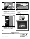
* KIT CONTENTS:
1 ea. Top Panel
1 ea. Left Side Panel
1 ea. Right Side Panel
6 ea. Magnets
* Note: Trim Kits with Brass and Stainless Finishes also include:
1 ea. Left Side Channel
1 ea. Right Side Channel
1 ea. Top Channel
Double-sided tape on panels
(If the kit you purchased includes channels and double-sided tape, they
should be used)
TOOLS REQUIRED:
None
INSTALLATION INSTRUCTIONS:
This kit contains trim panels used to finish the gaps between the wall-
board or optional mantel and the fireplace, providing the appliance a fin-
ished built-in look.
ENSURE FIREPLACE IS COOL TO THE TOUCH BEFORE STARTING IN-
STALLATION OF THE TRIM KIT
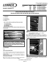
Step 1. Place 2 magnets on each side of the fireplace, placed at approxi-
mately 8” from the top and 8” from the base. See Figure 2.
Step 2.
Brass and Stainless Trim Kits - Proceed to Step 3.
Black Trim Kits - Proceed to Step 4.
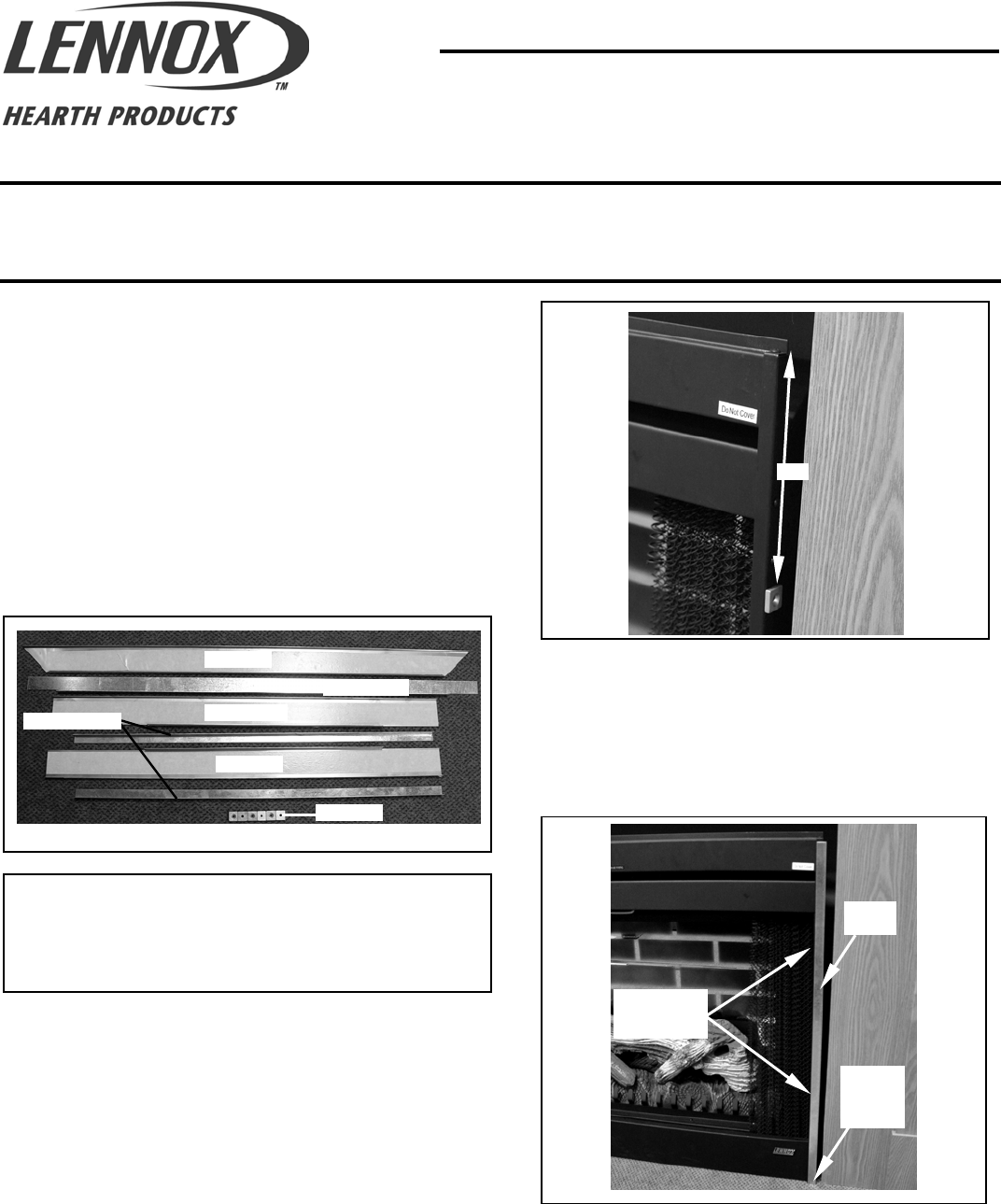
Step 3. Place the side channels over the magnets (See Figure 3 ).
Ensure that the two side channels are flush with the bottom of the
fireplace. The wider side of the side channel should be on the front of
the fireplace face after installation.
Step 3. Peel off the backing on the double-sided tape on the backside
of each side trim panel (see Figure 4 ). Avoid touching the sticky
surface of the tape.
CAUTION: CAREFULLY SEPARATE THE MAGNETS BY TWISTING
THEM APART. BE VERY CAREFUL WHEN HANDLING, BECAUSE
THE MAGNETS ARE VERY POWERFUL AND CAN SNAP TO-
GETHER UNEXPECTEDLY AND POSSIBLY PINCH THE SKIN OR
FRACTURE THE MAGNETS.
Left Panel
Right Panel
Top Panel
*Side Channels
Magnets
~
8”
Figure 1
Figure 2
Ensure
Channel is
Flush with
Base
Side
Channel
Figure 3
Approximate
Magnet
Placement
*Top Channel