27
LENNOX HEARTH PRODUCTS • MERIT
®
SERIES DIRECT-VENT GAS FIREPLACES • MODELS MLDVT-30/35/40/45 • CARE AND OPERATION INSTRUCTIONS
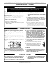
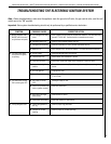
TROUBLESHOOTING THE ELECTRONIC IGNITION SYSTEM
SYMPTOM POSSIBLE CAUSES CORRECTIVE ACTION
Check voltage on AC terminals of module an/or batteries. The value should be
around 2.7 to 3.2 VAC. Confirm that wire connections are secure.
Check for visible cracked casing, cuts, etc.
Check pilot assembly for visibly broken spark electrode, etc.
Check voltage on D.C. terminal of batteries. The value should be around 3.0V
Ensure that the gas supply is turned on.
Ensure sensor wire connection is secure.
Ensure black, green and orange wires connection is secure to valve.
Ensure black sensor wire (S) and black igniter wire (I) is secure to ignition
module.
Purge gas line of air.
Test voltage at AC terminals of module and/or batteries. It should be around
2.7 to 3.2 VAC.
Turned gas supply to "ON".
Check wire connection.
Check location of sensor.
Check vent system for obstructions.
Check for proper log placement.
Check for proper air shutter openings.
A. Low voltage/or bad lead
wires.
B. Damaged igniter wire.
C. Damaged pilot assembly.
D. Batteries Low
A. No fuel supply.
B. Loose sensor wire.
C. Lose wires to valve.
D. Loose wires to ignition
module.
E. Air in the gas line.
F. Low voltage.
A. Gas supply is turned
"OFF".
B. Loose wire connection on
valve or ignition module.
C. Flame does not engulf
flame sensor.
D. Obstructed vent system.
A. Flame impingement on
the log.
B. Improper air shutter
opening.
1. Nothing happens when
ON/OFF switch is turned
on (pilot does not spark).
2. The main burner does
not light and the igniter
is sparking.
3. The main burner comes
"ON" but then goes "OFF".
4. The log and glass soot.
Note: Before troubleshooting, make sure the appliance main line gas shut-off valve, the gas control valve, and the wall
switch are in the “ON” position.
Important: Valve system troubleshooting should only be performed by a qualified service technician.


