


WARNING: TEST YOUR SMOKE ALARM OPERATION AFTER R.V. OR MOBILE HOME VEHICLE
HAS BEEN IN STORAGE, BEFORE EACH TRIP AND AT LEAST ONCE A WEEK DURING USE.
2.LOCATIONS TO AVOID
•In the garage. Products of combustion are present when you start your automobile.
• Less than 4” (10cm) from the peak of an “A” frame type ceiling.
•In an area where the temperature may fall below 40ºF or rise above 100ºF.
•In dusty areas. Dust particles may cause nuisance alarm or failure to alarm.
•In very humid areas. Moisture or steam can cause nuisance alarms.
•In insect-infested areas.
•Smokealarmsshould not beinstalledwithin 3ft(.9m)of the following: thedoor toakitchen, thedoor to abath-
room containingatub or shower,forced airducts used forheatingor cooling, ceilingorwhole houseventilating
fans, orotherhighair flow areas.
•Kitchens. Normal cooking may cause nuisance alarms. If a kitchen alarm is desired, it should have an alarm
silence feature or be a photoelectric type.
•Near fluorescent lights. Electronic “noise” may cause nuisance alarms.
3.INSTALLATION INSTRUCTIONS
WIRING REQUIREMENTS
• This smoke alarm should be installed on a U.L. listed or recognized junction box. All connections should be
made by a qualified electrician and must conform to article 760 of the U.S. National Electrical Code, NFPA 72
and/or any other codes having jurisdiction in your area.
• The appropriate power source is 120 Volt A.C. Single Phase supplied from a non-switchable circuit which is
not protected by a ground fault interrupter.
• The alarm should not be operated on power derived from a square wave, or modified square wave, inverter.
These power sources produce high peak voltages that will damage the alarm.
WIRING INSTRUCTIONS FOR A.C. QUICK CONNECT HARNESS
CAUTION! TURN OFF THE MAIN POWER TO THE CIRCUIT BEFORE WIRING THE ALARM.
• For alarms that are used as single station, DO NOT CONNECT THE RED WIRE TO ANYTHING. Leave the
red wire insulating cap in place to make certain that the red wire cannot contact any metal parts or the elec-
trical box.
•When alarms are interconnected, all interconnected units must be powered from a single circuit.
•A maximum of 24 Kidde devices may be interconnected in a multiple station arrangement. The interconnect
system should not exceed the NFPA interconnect limit of 12 smoke alarms and/or 18 alarms total (smoke,
heat, carbon monoxide, etc.) With 18 alarms interconnected, it is still possible to interconnect up to a total of
6 remote signaling devices and/or relay modules.
Caution! Kidde alarms and accessories CAN ONLY BE interconnected with other Kidde alarms and
accessories. Connection of these devices to another manufactures interconnect system,or con-
nection with equipment from another manufacturer into an existing Kidde system could result in
nuisance alarming,failure to alarm,or damage to one or all of the devices in the interconnect sys-
tem.
•When mixing models which have battery backup with models without battery backup, be advised that the
models without battery backup will not respond during an AC power failure.
•For more information about compatible interconnect units and their functionality in an interconnect system,
visit our web site at: www.KiddeUS.com
• The maximum wire run distance between the first and last unit in an interconnected system is 1000 feet.
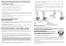
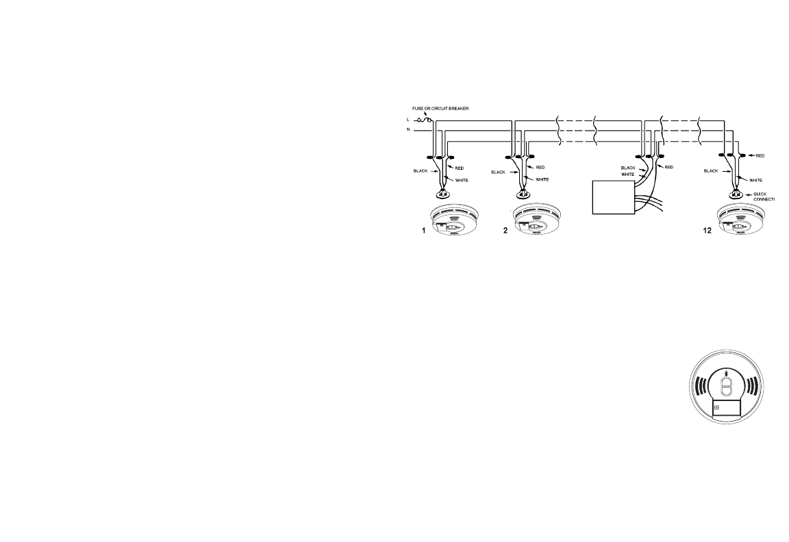
•Figure 1 illustrates interconnection wiring. Improper connection will result in damage to the alarm, failure to
operate, or a shock hazard.
•Make certain alarms are wired to a continuous (non-switched) power line. NOTE: Use standard UL listed
household wire (18 gauge or larger as required by local codes) available at all electrical supply stores and
most hardware stores.
FIGURE 1 INTERCONNECT WIRING DIAGRAM
WIRES ON ALARM HARNESS CONNECTED TO
Black Hot Side of A.C. Line
White Neutral Side of A.C. Line
Red Interconnect Lines (Red Wires) of Other
Units in the Multiple Station Set up
BATTERY INSTALLATION
See MAINTENANCE (Section 6) for battery installation.
CAUTION! THIS UNIT WILL NOT FUNCTION WITHOUT A PROPERLY INSTALLED BATTERY, AND IS EQUIPPED
WITH A BATTERY LOCKOUT FEATURE WHICH PREVENTS THE BATTERY CARRIER
FROM CLOSING IF A BATTERY IS NOT INSTALLED CORRECTLY.
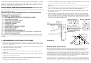
MOUNTING INSTRUCTIONS
CAUTION: THIS UNIT IS SEALED. THE COVER IS NOT REMOVABLE!
CAUTION: WHEN WALL MOUNTING: UNIT MUST BE MOUNTED SO
THAT BATTERY BOX FACES DOWN! (SEE FIGURE 1A)
1. Remove the trim ring from the back of the alarm by holding the trim
ring and twisting the alarm counter-clockwise.
2. After selecting the proper smoke alarm location as described in Section 1 and wiring the AC
Quick Connector as described in the WIRING INSTRUCTIONS, attach the trim ring to the electrical
box (see Figure 2). To ensure aesthetic alignment of the alarm with the hallway or wall, the “A” line
on the mounting bracket must be parallel with the hallway when ceiling mounted, or horizontal
when wall mounted.
3. Pull the AC QUICK CONNECTOR through the center hole in the mounting bracket and secure
the bracket, making sure that the mounting screws are positioned in the small ends of the keyholes
before tightening the screws.
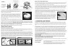
Optional Accessory
KIDDE
Relay Module
Model SM120X
FIGURE 1A