


2
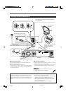
Parts Identification
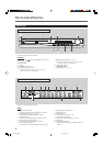
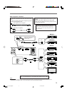
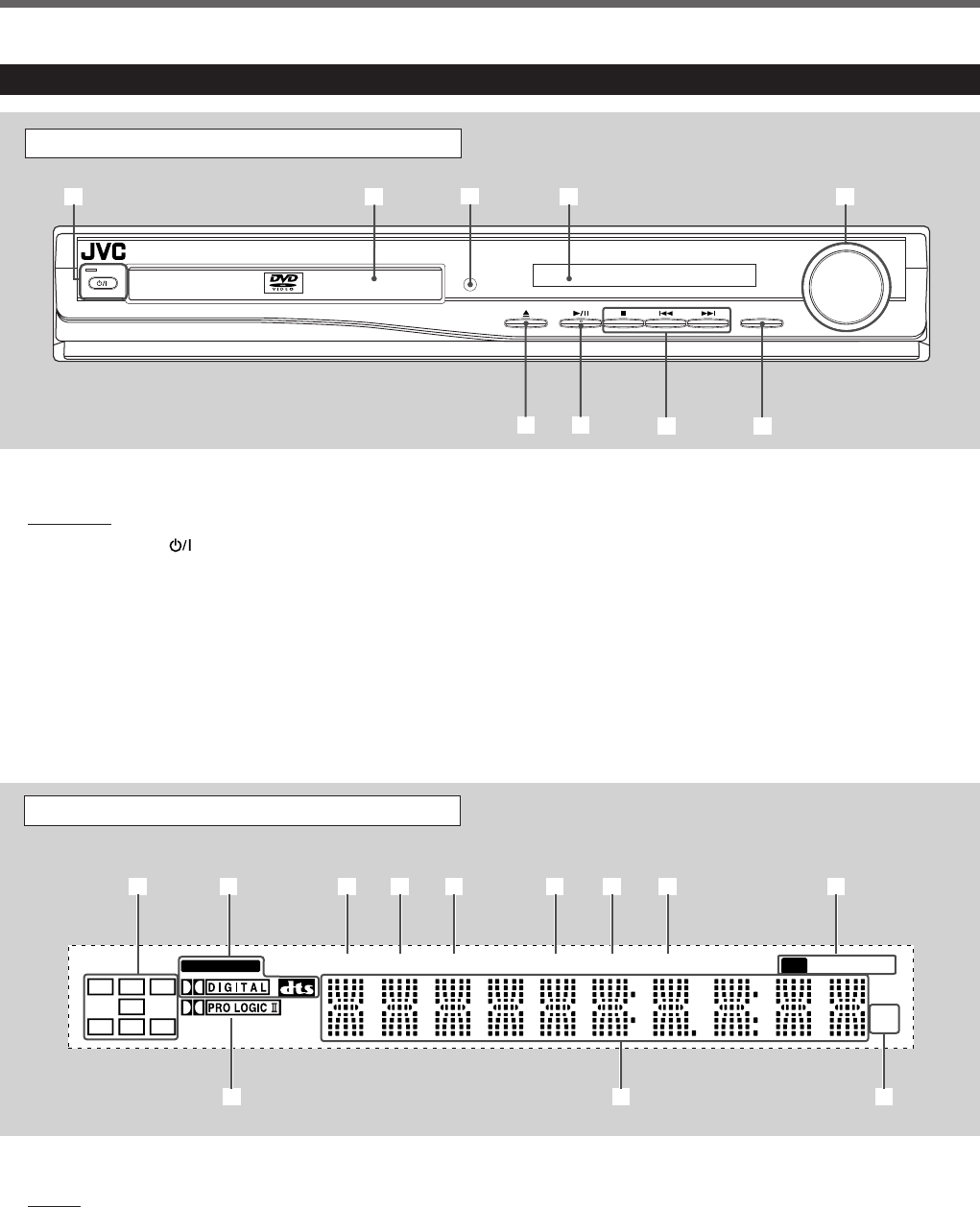
Front Panel
See pages in the parentheses for details.
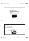
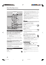
Display
1 Audio channel indicators
• Indicates audio channels currently being reproduced.
2 Digital signal indicators (11, 17, 18)
• LINEAR PCM, DOLBY DIGITAL, and DTS.
3 TITLE indicator (11)
• Indicates the current title number with main display.
4 PBC (Play Back Control) indicator
• Goes on when the PBC function is activated.
5 CHAP (chapter) indicator (11)
• Indicates the current chapter number with main display.
6 PRGM (program) indicator (33)
7 RDS indicator (34)
8 RT indicator (34)
9 Tuner mode indicators (13, 32, 33)
• ST (stereo) and TUNED
p Dolby PRO LOGIC II indicator (11, 17, 18)
q Main display
w Frequency unit indicators
• kHz (for AM band station) and MHz (for FM band
station)
Display
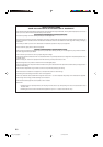
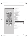
Center Unit
See pages in the parentheses for details.
Front Panel
1 STANDBY/ON button and STANDBY lamp (10–13)
2 Disc tray (10)
3 Remote sensor
4 Display
5 VOLUME control (11, 13)
6 0 (open/close) button (10, 12)
• Pressing this button also turns on the power and
changes the source to the DVD/CD.
7 3/8 (play/pause) button (11, 12, 29)
• Pressing this button also turns on the power and
changes the source to the DVD/CD.
8 Multi operation buttons
• 4, ¢, and 7
9 SOURCE button (10, 13, 14)
VOLUME
SOURCE
STANDBY
STANDBY/ON
DVD DIGITAL CINEMA SYSTEM TH-A25
2
6 7
98
4 5
3
1
RT
MHz
k
Hz
RDS
PRGM
CHAP TUNEDPBC
TITLE
LINEAR PCM
ST
L C R
SW
LS
S RS
1
wp
5 63 42 7 8 9
q
01_09_TH_A25[B].p65 03.7.28, 8:05 PM2