


368262-UIM-B-1008
EFFICIENCY
RATING
CERTIFIED
ISO9001
CertifiedQuality
ManagementSystem
RESIDENTIAL GAS FURNACE
WITH ECM MOTOR
MODELS:
TP8C/TPLC*MP, YP8C/YPLC*MP,
CP8C/CPLC*MP, LP8C/LPLC*MP
(80% Modulating Multi-position / Low NOx)
INSTALLATION MANUAL
LIST OF SECTIONS
SAFETY . . . . . . . . . . . . . . . . . . . . . . . . . . . . . . . . . . . . . . . . . . . 1
DUCTWORK . . . . . . . . . . . . . . . . . . . . . . . . . . . . . . . . . . . . . . . . 5
FILTERS . . . . . . . . . . . . . . . . . . . . . . . . . . . . . . . . . . . . . . . . . . . 9
GAS PIPING . . . . . . . . . . . . . . . . . . . . . . . . . . . . . . . . . . . . . . . 10
ELECTRICAL POWER . . . . . . . . . . . . . . . . . . . . . . . . . . . . . . . 11
VENT SYSTEM . . . . . . . . . . . . . . . . . . . . . . . . . . . . . . . . . . . . . 19
START-UP AND ADJUSTMENTS . . . . . . . . . . . . . . . . . . . . . . 22
SAFETY CONTROLS . . . . . . . . . . . . . . . . . . . . . . . . . . . . . . . . 28
NORMAL OPERATION AND DIAGNOSTICS . . . . . . . . . . . . . 29
REPLACEMENT PARTS LIST . . . . . . . . . . . . . . . . . . . . . . . . . 30
REPLACEMENT PART CONTACT INFORMATION . . . . . . . . 30
WIRING DIAGRAM . . . . . . . . . . . . . . . . . . . . . . . . . . . . . . . . . . 31
LIST OF FIGURES
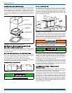
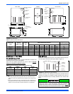
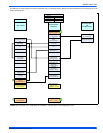
Duct Attachment . . . . . . . . . . . . . . . . . . . . . . . . . . . . . . . . . . . . . . . . . 5
Combustible Floor Base Accessory . . . . . . . . . . . . . . . . . . . . . . . . . . 6
Horizontal Application (Typical) . . . . . . . . . . . . . . . . . . . . . . . . . . . . . 6
Typical Attic Installation . . . . . . . . . . . . . . . . . . . . . . . . . . . . . . . . . . . 6
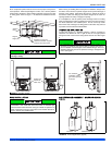
Typical Suspended Furnace / Crawl Space Installation . . . . . . . . . . . 7
Downflow Venting . . . . . . . . . . . . . . . . . . . . . . . . . . . . . . . . . . . . . . . 7
Downflow Installation - Gas Valve Rotation . . . . . . . . . . . . . . . . . . . . 7
Vertical Applications (Typical) . . . . . . . . . . . . . . . . . . . . . . . . . . . . . . 7
Coil Flange . . . . . . . . . . . . . . . . . . . . . . . . . . . . . . . . . . . . . . . . . . . . . 8
Horizontal Right Application (Typical) . . . . . . . . . . . . . . . . . . . . . . . . 8
Horizontal Left Application . . . . . . . . . . . . . . . . . . . . . . . . . . . . . . . . . 8
PC Series Upflow Coil Installation . . . . . . . . . . . . . . . . . . . . . . . . . . . 8
Horizontal Left or Right application (Right Shown) . . . . . . . . . . . . . . 8
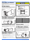
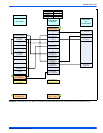
Dimensions . . . . . . . . . . . . . . . . . . . . . . . . . . . . . . . . . . . . . . . . . . . . 9
Side Return Cutout Markings . . . . . . . . . . . . . . . . . . . . . . . . . . . . . . . 9
Gas Valve . . . . . . . . . . . . . . . . . . . . . . . . . . . . . . . . . . . . . . . . . . . . . 10
Upflow/Downflow Gas Piping . . . . . . . . . . . . . . . . . . . . . . . . . . . . . . 10
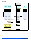
Electrical Wiring . . . . . . . . . . . . . . . . . . . . . . . . . . . . . . . . . . . . . . . . 12
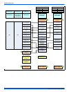
Thermostat Chart - Single Stage Air Conditioner –
Variable Speed or PSC Modulating Furnace . . . . . . . . . . . . . . . . . .13
Thermostat Chart - Two Stage Air Conditioner –
Variable Speed or PSC Modulating Furnace . . . . . . . . . . . . . . . . . .14
Thermostat Chart - Two Stage Air Conditioner with Single Stage
Thermostat – Variable Speed or PSC Modulating Furnace . . . . . . .15
Thermostat Chart - Single Stage Heat Pump –
Variable Speed or PSC Modulating Furnace . . . . . . . . . . . . . . . . . .16
Thermostat Chart - Single Stage Heat Pump –
Variable Speed or PSC Modulating Furnace . . . . . . . . . . . . . . . . . .17
Thermostat Chart - Two Stage Heat Pump –
Variable Speed or PSC Modulating Furnace . . . . . . . . . . . . . . . . . .18
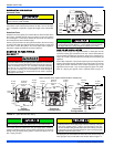
Combustion Air Inducer . . . . . . . . . . . . . . . . . . . . . . . . . . . . . . . . . .19
Combustion Airflow Path Through The Furnace Casing
to the Burner Compartment . . . . . . . . . . . . . . . . . . . . . . . . . . . . . . .20
Outside and Ambient Combustion Air . . . . . . . . . . . . . . . . . . . . . . . .21
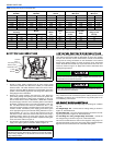
Gas Valve . . . . . . . . . . . . . . . . . . . . . . . . . . . . . . . . . . . . . . . . . . . . .25
Furnace Control Board . . . . . . . . . . . . . . . . . . . . . . . . . . . . . . . . . . .26
Wiring Diagram . . . . . . . . . . . . . . . . . . . . . . . . . . . . . . . . . . . . . . . . .31
LIST OF TABLES
Unit Clearances to Combustibles . . . . . . . . . . . . . . . . . . . . . . . . . . . . 4
Coil Projection Dimensions - PC Series Coils . . . . . . . . . . . . . . . . . . 8
Cabinet and Duct Dimensions . . . . . . . . . . . . . . . . . . . . . . . . . . . . . . 9
Recommended Filter Sizes (High Velocity 600 FPM) . . . . . . . . . . . . 9
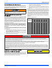
High Altitude Orifices . . . . . . . . . . . . . . . . . . . . . . . . . . . . . . . . . . . . 11
Ratings & Physical / Electrical Data . . . . . . . . . . . . . . . . . . . . . . . . . 12
Estimated Free Area . . . . . . . . . . . . . . . . . . . . . . . . . . . . . . . . . . . . 20
Unconfined Space Minimum Area in Square Inch . . . . . . . . . . . . . .20
Free Area . . . . . . . . . . . . . . . . . . . . . . . . . . . . . . . . . . . . . . . . . . . . .20
Gas Rate (CU FT/HR) at Full Input . . . . . . . . . . . . . . . . . . . . . . . . . .24
Inlet Gas Pressure Range . . . . . . . . . . . . . . . . . . . . . . . . . . . . . . . .25
Nominal Manifold Pressure . . . . . . . . . . . . . . . . . . . . . . . . . . . . . . . .25
Blower Performance CFM - Any Position . . . . . . . . . . . . . . . . . . . . .27
These high efficiency, compact units employ induced combustion, reli-
able hot surface ignition and high heat transfer aluminized tubular heat
exchangers. The units are factory shipped for installation in upflow or
horizontal applications and may be converted for downflow applica-
tions.
These furnaces are designed for residential installation in a basement,
closet, alcove, attic, recreation room or garage and are also ideal for
commercial applications. All units are factory assembled, wired and
tested to assure safe dependable and economical installation and oper-
ation.
These units are Category I listed and may be common vented with
another gas appliance as allowed by the National Fuel Gas Code.
SECTION I: SAFETY
This is a safety alert symbol. When you see this symbol on
labels or in manuals, be alert to the potential for personal
injury.
Understand and pay particular attention to the signal words DANGER,
WARNING, or CAUTION.
DANGER indicates an imminently hazardous situation, which, if not
avoided, will result in death or serious injury
.
WARNING indicates a potentially hazardous situation, which, if not
avoided, could result in death or serious injury
.
CAUTION indicates a potentially hazardous situation, which, if not
avoided may result in minor or moderate injury.
It is also used to
alert against unsafe practices and hazards involving only property dam-
age.