


NOTES:
1. If the furnace is equipped with NOx screens and is to be
used with LP (propane) gas, the screens must be removed
prior to start-up.
2. Drip leg in the gas line must be installed.
3. The furnace controls require correct polarity on the power
supply and a proper ground.
4. Y & G must be connected to the control board for cooling
operation.
5. External filters are required on all configurations.
6. Electrical or gas entry is available on both casing sides.
7. To measure total static pressure, add supply duct pressure
to the return duct pressure, add pressure drop across the ‘A’
coil, and add pressure drop across the filter. Ignore negative
signs on the readings.
8. Inlet gas pressure should be 7” w.c. for natural gas and 11”
w.c. for propane. Nominal manifold gas pressure is 3.5” w.c.
for natural gas and 10” w.c. for propane at max. input.
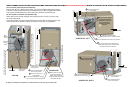
9. For downflow application the vent blower must be rotated 90
left or right as shown.
†
Other airflows are available. see Tech Guide for all CFM options.
* Cool Tap.
** Adjustment Tap.
LED INDICATOR
Slow Green Flash - Normal operation in standby mode.
Slow Amber Flash - Normal operation with call for cooling.
Two Amber Flashes - Normal operation with call for heat.
Three Amber Flashes - Normal operation, burner is on at end of
thermostat cycle.
Six Amber Flashes - Normal operation with call for heat pump
heating.
Any Red Flash - Fault condition. NOTE: 4 or 5 flashes may indi-
cate a blown fuse on the circuit board.
Models
Airflow CFM (Bottom Return without Filters)
Minimum Wire
Size awg @ 75'
One-Way
Maximum
Over Current
Protection
0.5" ESP (Nominal)
†
*D-A** *C-A** *B-A** *A-B**
TM9V060B12MP11
600 690 1000 1305 14 15
TM9V080B12MP11
600 680 1000 1290 14 15
TM9V080C16MP11
850 905 1175 1670 14 15
TM9V100C16MP11
870 910 1160 1655 14 15
TM9V100C20MP11
960 1155 1605 2215 12 20
TM9V120D20MP11
960 1160 1595 2180 12 20
Models
Input
Rate
Total Unit
Amps
Air Temp. Rise
Max Input °F
Air Temp. Rise
Min Input °F
Time For 1 ft
3
Natural Gas
(1030 Btu/Ft
3
) Seconds
(On Max. Rate)
Max Min
TM9V060B12MP11 60,000 21,000 9 35 - 65 35 - 65 62
TM9V080B12MP11 80,000 28,000 9 35 - 65 30 - 60 46
TM9V080C16MP11 80,000 28,000 12 35 - 65 35 - 65 46
TM9V100C16MP11 100,000 35,000 12 35 - 65 30 - 60 37
TM9V100C20MP11 100,000 35,000 14 35 - 65 35 - 65 37
TM9V120D20MP11 120,000 42,000 14 35 - 65 35 - 65 31
This document does not replace the installation instructions, which must be referred to for
detailed information.
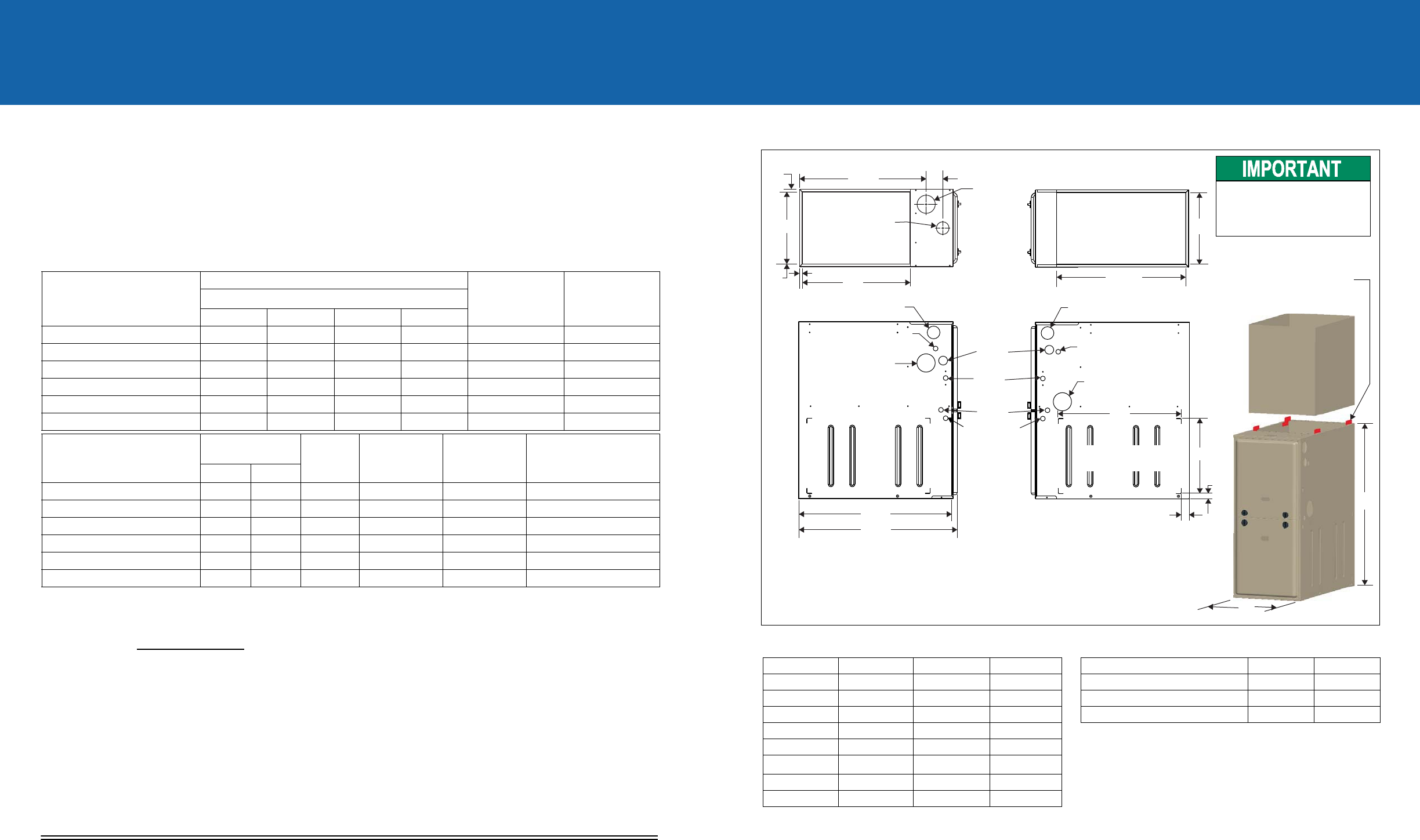
CLEARANCES
* 24" clearance in front and 18" on side recommended for
service access.
All furnaces approved for alcove and attic installation.
DIMENSIONS
SUPPLY END
RETURN END
LEFT SIDE
Combustion Air Inlet
Condensate Drain
(Downflow)
Vent Connection
Outlet
Thermostat
Wiring
29.5”
28.5”
RIGHT SIDE
Condensate Drain
(Downflow)
14”
1”
1.5”
23”
Combustion Air Inlet
Gas Pipe
Entry
Electrical
Entry
Condensate
Drain
Optional Return Air
Cutout (Either side)
FRONT
A
33”
Clips can be flipped
into the up position
for coil cabinet or
plenum attachment
A-COIL
Follow all national and local codes and standards in addition to this document.
The installation must comply with regulations of the serving gas supplier, local building,
heating, plumbing,and othercodes. Inabsence oflocal codes,the installation mustcomply
with national codes and all authorities having jurisdiction.
B
24.25”
.56”
.56”
20”
3”
23.8”
.56”
Combustion
Air Inlet
2” Diameter
Vent Connection
Outlet
B
DURING INSTALLATION,
DOORS MUST REMAIN ON
FURNACE WHEN MOVING
OR LIFTING.
Vent Connection
Outlet
Application Upflow Downflow Horizontal
Top 1" 0" 0"
Vent 0" 0" 0"
Rear 0" 0" 0"
Side 0" 0" 1"
Front* 0" 0" 0"
Floor Combustible
Combustible
1
1. For combustible floors only when used with special
sub-base.
Combustible
Closet Yes Yes Yes
Line Contact No No Yes
Cabinet Size A (in) B (in)
All 'B' Cabinet Furnaces 17-1/2" 16-3/8"
All 'C' Cabinet Furnaces 21" 19-7/8"
All 'D' Cabinet Furnaces 24-1/2" 23-3/8"
QUICK REFERENCE GUIDE
96%TWO STAGE MULTI-POSITION RESIDENTAL
GAS FURNACES (33” TALL)
Subject to change without notice. Printed in U.S.A. 438336-URG-A-0209
Copyright © 2009 by Johnson Controls, Inc. All rights reserved. Supersedes: Nothing
Johnson Controls Unitary Products
5005 York Drive
Norman, OK 73069
*438336*