


E2000 D PRINTED IN U.S.A.
&
(419) 636-4242
D
F
AX (419) 633-1674
INGERSOLL-RAND COMPANY
P.O.BOX 151 DONE AROCENTER DBRYAN, OHIO43506Ć0151
OPERATOR’S
MANUAL
651702
RELEASED: 3-16-94
REVISED: 9-15-00
(REV.
B)
651702
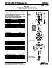
DOWNSTREAM MATERIAL REGULATOR
INCLUDE OPERATOR'S MANUAL: 65179XĆXĆB LOW PRESSURE MATERIAL REGULATOR (PN 97999Ć552)
1-1/4” NPTF ST
AINLESS STEEL W / TC SEA
T
MAXIMUM PRESSURE RATING: 1,250 PS1 (86 BAR)
MAXIMUM REGULATED PRESSURE RATING: 60 PSI (4.2 BAR)
Model 651702 is similar to other models in the Standard Low PresĆ
sure Downstream Regulator Series.
In this model the Valve Section has a larger (40) stem, (44) spring,
(43) ball and the large inlet / outlet (48) base etc.
The 65179XĆXĆB Operator's Manual needs to be used for General
Information, Installation, Operation and Maintenance.
651702 PARTS LIST
ITEM DESCRIPTION(Size inInches) PART NO.
QTY
n Diaphragm Service Kit Parts 62173
f Seat Kit Parts 61967Ć1
1 Housing 93534Ć1 (1)
2 Bolt (7/16"x5") 93487Ć2 (4)
3 Washer (7/16") Y79Ć716 (4)
4 Washer (1.173o.d. x.119Thk) 93485Ć1 (1)
5 Thrust Bearing (1.173o.d.) 93484Ć1 (1)
6 Adjusting Screw (5/8" Ć24,Left Hand) 93486Ć1 (1)
7 Plate 93818 (1)
8 Adjusting Nut 93481Ć1 (1)
9 Spring (Gray) 93638Ć1 (1)
10 Screw (#10Ć32x 7/8") Y191Ć107 (1)
11 Lock Washer (#10) Y14Ć10 (1)
13 Small Plate 93893 (1)
14 Button 93889 (1)
15 Plate 93633Ć2 (1)
n16 Diaphragm (.062"Thick, black) 93883 (1)
n17 Diaphragm (.020"Thick, white) 93630Ć1 (1)
n18 O" Ring(3/32" x1Ć7/8" o.d.) Y328Ć131 (1)
40 ValveStem 93975 (1)
f41 O" Ring(1/16" x15/16" o.d.) Y328Ć19 (1)
f42 Seat 93522Ć1 (1)
43 Ball 93510Ć1 (1)
44 Spring 93480Ć1 (1)
45 Flow Tube 93490Ć1 (1)
47 Base Plug (Includes(46) O"Ring) 61957Ć1 (1)
48 Base 93655Ć2 (1)
51 Coupling (1/4"NPT) (Not Shown) Y43Ć242ĆS (1)
52 Nipple (1/4" NPTx 4")(Not Shown) Y44Ć15ĆS (1)
53 Wrench, Allen (3/16")(Not Shown) Y106Ć109 (1)
54 Screw (NotShown) 93819 (1)
55 Nut (7/16"Ć 20)(Not Shown) Y11Ć7ĆC (2)
56 Lockwasher (7/16")(Not Shown) Y14Ć716 (1)
57 Stud (Not Shown) 92987 (1)
PN97999Ć611
11
14
15
16 (BLACK)
17 (WHITE)
18
13
3
1
7
6
8
4
5
2
UPPER
REGULATOR
SECTION
40
48
VALVE SECTION
41
42
43
44
47
45
46
9
10
Note: Refer to the standard
65179XĆXĆB Operator'sĆ
Manual for Torque SpecifiĆ
cations and other service
information.