


All units are provided with right hand rotation unless otherwise
specified. This means that hose is pulled off spool top left or
bottom right (spool rotates clockwise to wind hose) when
viewing spring end of reel. See diagram on parts page.
Clock-type springs provide power for automatic hose take-up.
Spring must be pretensioned at time of installation to
insure that tension is applied to hose at all times. A tension
adjustment spanner wrench is provided with each reel.
INSTALLATION
1. Install hose if reel was purchased without hose. See
instructions on page 4.
2. Insure that machinery to be serviced by reel is at
position closest to reel.
☞
2. Securely mount reel in desired position using 1/2"(M12).
Be sure spool is aligned with hose run.
☞
3. Position hose guide if supplied so hose pays-out as
straight as possible through hose guide.
☞
4. Connect free end of hose to connections on machine or
adjust hose stop so that desired length of hose extends from reel.
☞
5. Connect flexible supply lines to swivel fitting. See HOSE
INSTALLATION REFERENCE DRAWING.
NOTE: Do not hard plumb to swivel fitting.
☞
6. Remove cover plate on spring housing to expose
shaft and spring hub. (See Figure 1).
☞
7. Insert spanner wrench into holes in spring hub (Fig 2).
Rotate spanner wrench counter-clockwise. Number of
360˚ turns should match last digit in model number on
serial plate.
MAINTENANCE
Periodically: A. Inspect hose
for wear and check mounting
bolts and other hardware for
tightness.
B. Check for broken springs
by pulling about 2/3 hose off
reel and observing “Broken
Spring Indicators” on sides of
spring canisters (Fig. 3).
NOTE: Bearings and springs are prelubricated and require no
periodic maintenance.
SPRING REPLACEMENT
The unique SAFETYCHANGE® spring motor consists of a
spring and hub sealed within a housing. A replacement spring
is supplied sealed in its housing and the old unit should be
discarded completely.
☞
1. Turn off supply pressure to reel.
2. Insure that machinery to be serviced by reel is at
position closest to reel. Disconnect hose from
machine connections.
☞
3. Wind all hose onto reel to relieve all spring tension.
☞
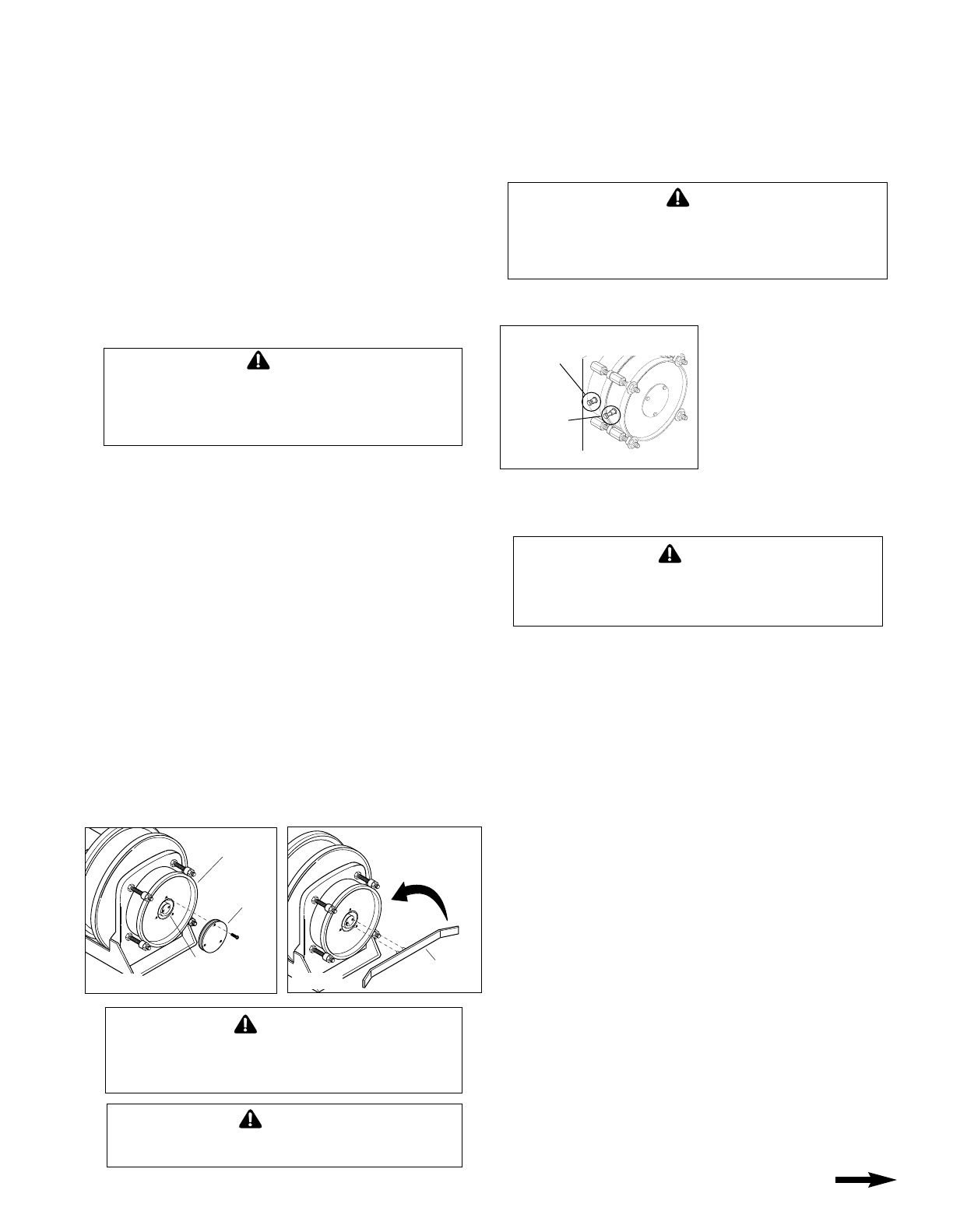
4. Remove inspection cover from face of spring housing.
☞
5. Rotate spool clockwise and observe inner shaft.
Shaft should rotate clockwise and hub (with
spring attached) should remain stationary.
NOTE: Do not attempt to remove spring if resistance is
met or hub tends to rotate with shaft. Continue to rotate
spool and strike end of shaft several sharp blows with a lead
hammer or rubber mallet until shaft rotates freely
and hub remains stationary.
☞
6. Remove (4) bolts which secure spring motor to frame.
☞
7. Slide spring motor off shaft and discard.
☞
8. Install replacement spring motor, pawls and pawl springs.
NOTE: Pawl springs must be located between the pawls
and the deepest section of the shaft grooves.
Make sure that pawls and pawl springs are inserted flush
with ends of shaft and hub or they may rub against
inspection cover. See Fig 4, page 4.
If machine pull reel, move machinery to position closest
to reel before adjusting spring tension.
Adjusting tension with hose extended may result in
damage to reel or personal injury.
WARNING
Do not attempt to remove spring from its housing. Clock-
type springs can be dangerous to handle. Removal of
spring from housing could result in personal injury.
WARNING
Do not exceed number of turns indicated on serial plate.
Over-tensioning can cause a broken spring, sheared
shaft or other damage.
CAUTION
CONTINUED ON BACK PAGE
INSTALLATION and MAINTENANCE INSTRUCTIONS
UH18 UNIVERSAL HOSE REEL-DIRECT DRIVE
NOTE: These instructions are written for machine pull reels.
☞If installing or servicing hand pull reel, use only those steps marked with hand
☞
.
COVER
PLATE
SPRING
HUB
SPRING
HOUSING
COUNTER-
CLOCKWISE
FOR STANDARD
ROTATION
SPANNER
WRENCH
Figure 1
Figure 2
Do not attempt to relieve spring tension using spanner
wrench. Doing so may result in personal injury.
WARNING
Some reels with large or multiple springs are equipped with
a ratcheted adjustment wrench. Follow separate instruc-
tions for its use. Failure to use ratcheted wrench, on reels
so equipped, could result in serious personal injury.
WARNING
BROKEN SPRING
INDICATORS
“IN” with 2/3
cable off reel–
SPRING OK
“OUT” with 2/3
cable off reel–
SPRING
BROKEN
Figure 3
☞
9. Tighten bolts securing spring housing to reel frame.
☞
10. Connect free end of hose to connections on machine
or adjust hose stop so that desired length of hose
extends from reel.
11. Tension spring with spanner wrench. Refer to
INSTALLATION section.
☞
12. Replace inspection cover.
HOSE REMOVAL
Use the following procedure to remove worn or damaged hose
from reel prior to installation of new hose.
1. Move machine serviced by reel to a position closest to
reel. Spring will still be under pre-tension at this point.
☞2. Turn off supply pressure to reel.
☞3. Disconnect hose from machine or other attachments.
Remove hose stop, if installed, and allow hose to
retract onto spool. Ensure all tension is off spring by
manually rotating spool (normally clockwise when
viewed from spring side).
☞4. Unwrap hose without allowing spool to turn.
☞5. Disconnect hose from elbows inside spool wrapper.
☞6. Install new hose following directions below.
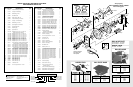
HOSE INSTALLATION
Use the following procedure to replace hose or if reel was
ordered without hose. Refer to HOSE INSTALLATION
REFERENCE DRAWING, below.
☞1. Unspool new hose from shipping spool and lay out to
eliminate twist.
NOTE: This step is not essential, but will aid in winding
operation of the reel and prolong hose life.
☞2. Insert hose end through guide and connect to elbows
inside spool wrapper. (See drawing below.)
☞5. Wind the hose onto the reel spool by hand rotating
spool in direction it turns free of spring tension.
(Normally clockwise when viewed from spring side)
☞6. Adjust hose stop (not used on machine pull reel).
☞7. Complete working end connections.
☞8. Pretension reel and complete installation as
described in REEL INSTALLATION section.
MOUNTING
BASE
HOSE STOP
ATTACH SUPPLY LINE HERE
NOTE: SUPPLY MUST BE
FLEXIBLE LINE. DO NOT
HARD PLUMB.
SWIVEL
FITTING
HOSE ON
SPOOL
ELBOW–
CONNECT
SPOOLED
HOSE HERE
ADJUSTABLE
HOSE STOP
SPOOL
WRAPPER
SECTIONS
SPOOL
DISK
SPOOL
DISK
HORIZONTAL HOSE
GUIDE POSITION
(STANDARD)
STANDARD SPOOL
ROTATION DIRECTION
TO WIND HOSE WHEN
VIEWED FROM
SPRING SIDE
STANDARD SPOOL
ROTATION DIRECTION
TO WIND HOSE WHEN
VIEWED FROM
FITTING SIDE
SPRING
MOTOR
OPTIONAL
VERTICAL
HOSE GUIDE
LOCATION–
REEL
MOUNTED
BASE UP
OPTIONAL
HORIZONTAL
HOSE GUIDE
LOCATION
HOSE INSTALLATION REFERENCE DRAWING
VIEW FROM SPRING SIDEVIEW FROM FITTING SIDE
Printed in USA Bulletin No. 042868.b
®
HUBBELL
®
A Hubbell Company
GLEASON REEL CORP.
P.O. Box 26 • 600 South Clark St.
Mayville, WI 53050–0026
Phone 920–387–4120 • Fax 920–387–4189
PAWL
SIDE VIEW
END VIEW
SPRING
Install
against flat
SPRING HUB
(Spring not
shown)
SHAFT
GROOVE
SPOOL
SHAFT
Figure 4