


® U.S. Registered Trademark
Copyright © 2004 Honeywell • • All Rights Reserved
INSTALLATION INSTRUCTIONS
69-0925-4
T8501
Microelectronic Thermostats
APPLICATION
The T8501 Microelectronic Thermostats provides electronic control of 24 Vac single-stage heating and cooling
systems. Refer to Table 1 for a general description of the thermostat. All T8501 thermostats require a common wire to
supply power.
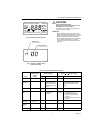
MERCURY NOTICE
If this control is replacing a control that contains
mercury in a sealed tube, do not place your old
control in the trash. Dispose of properly.
Contact your local waste management authority
for instructions regarding recycling and the
proper disposal of the old control.
INSTALLATION
When Installing this Product...
1. Read these instructions carefully. Failure to follow
the instructions can damage the product or cause
a hazardous condition.
2. Check the ratings given in the instructions and on
the product to make sure the product is suitable for
your application.
3. Installer must be a trained, experienced service
technician.
4. After completing installation, use these instructions
to check out the product operation.
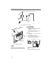
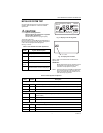
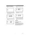
Location
Install the thermostat about 1.5m (5 ft) above the floor in
an area with good air circulation at average temperature.
See Fig. 1.
Do not install the thermostat where it can be affected by:
— drafts, or dead spots behind doors and in corners.
— hot or cold air from ducts.
— radiant heat from sun or appliances.
— concealed pipes and chimneys.
— unheated (uncooled) areas such as an outside wall
behind the thermostat.
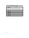
Wallplate Installation
The thermostat can be mounted horizontally on the wall
or on a 2 in. x 4 in. (50.8 mm x 101.6 mm) wiring box.
Position wallplate horizontally on the wall or on a
2 in. x 4 in. (50.8 mm x 101.6 mm) wiring box.
1. Position and level the wallplate (for appearance
only). The thermostat will function properly even
when not level.
2. Use a pencil to mark the mounting holes.
See Fig. 2.
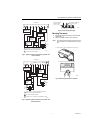
3. Remove the wallplate from the wall and drill two
3/16 inch (76 mm) holes in the wall (if drywall) as
marked. For firmer material such as plaster, drill
two 7/32 inch (5.56 mm) holes. Gently tap anchors
(provided) into the drilled holes until flush with the
wall.
4. Position the wallplate over the holes, pulling wires
through the wiring opening.
5. Loosely insert the mounting screws into the holes.
6. Tighten mounting screws.
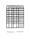
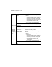
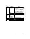
Table 1. Description of T8501 Thermostats.
System Changeover System Selection
Fan
Selection Comments
Heat-Cool Automatic Heat-Off-Cool-Auto On-Auto System and fan selections are done by
keyboard.