


® U.S. Registered Trademark
Copyright © 2002 Honeywell • •All Rights Reserved
INSTALLATION INSTRUCTIONS
69-1481-1
T8411R Electronic
Heat Pump Thermostat
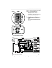
The T8411R Heat Pump Thermostat provides 24V
control of two-stage heating and one-stage cooling heat
pump system with manual changeover from heat to cool.
First stage heating and cooling cycle rates are fixed at
3 cph. Second stage heating cycle rate is selectable at
3, 4, 5, 6, or 9 cph. Temperature indication can be set for
°F or °C.
The T8411R Heat Pump Thermostat is powered directly
from the system transformer. Batteries are not required
because setpoints are held permanently by non-volatile
memory.
The T8411R TRADELINE® model includes a thermostat,
wallplate (for wiring and mounting thermostat), and
owner’s guide. A 7 3/8 in. x 5 3/4 in. (188mm x146 mm)
decorator cover plate (for covering wall marks) is
available separately. Order Honeywell part no. 209649A
(taupe color).
MERCURY NOTICE
If this control is replacing a control that contains
mercury in a sealed tube, do not place your old
control in the trash.
Contact your local waste management authority
for instructions regarding recycling and the
proper disposal of an old control containing
mercury in a sealed tube.
INSTALLATION
When Installing this Product…
1. Read these instructions carefully. Failure to follow
them could damage the product or cause a hazard-
ous condition.
2. Check the ratings given in the instructions and on
the product to make sure the product is suitable for
your application.
3. Installer must be a trained, experienced service
technician.
4. After installation is complete, check out product
operation as provided in these instructions.
CAUTION
Electrical Shock or Equipment Damage
Hazard.
Can shock individuals or short equipment
circuitry.
Disconnect power supply before installation.
Location
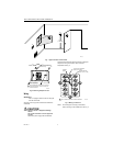
Install the thermostat about 5 ft (1.5m) above the floor in
an area with good air circulation at average temperature.
See Fig. 1. Do not install the thermostat where it can be
affected by:
— drafts or dead spots behind doors and in corners.
— hot or cold air from ducts.
— radiant heat from the sun or appliances.
— concealed pipes and chimneys.
— unheated (uncooled) areas such as an outside wall
behind the thermostat.
This thermostat is a precision instrument and was
carefully adjusted at the factory. Handle it carefully.
Mounting Wallplate to Wall
IMPORTANT
Level only for appearance. The thermostat func-
tions normally even when not level.
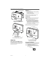
Mount wallplate, T8411R and the screws provided (see
Fig. 2) as follows:
1. Place the wallplate at the desired location on the
wall.
2. Use a pencil to mark the mounting holes.
3. Remove the wallplate from the wall and drill two
3/16 in. holes in the wall (if drywall) or two 7/32 in.
holes for firmer material such as plaster or wood.
4. Gently tap the anchors (provided) into the holes
until flush with the wall.
5. Position the wallplate over the holes.
6. Pull the thermostat wire through the wallplate
entrance hole.
7. Fasten the wallplate to the wall using the anchors
and screws provided.