


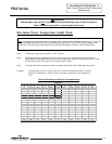
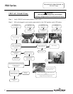
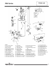
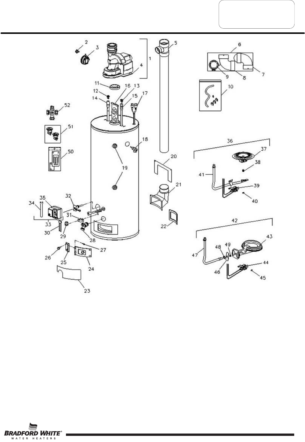
Parts List
1. Blower Assembly
2. Blower Temp. Switch
3. Pressure Switch
4. Blower Gasket
5. Tee and Vent Pipe Assy.
6. Vent Adapter with Term.
7. Intake Terminal
8. Vent Terminal Elbow
9. Exhaust Adapter
10. Condensate Hose Kit
11. Flue Reducer
12. Heat Trap Insert (outlet)
13. Heat Trap Insert (inlet)
14. Hot Water Outlet Anode
15. Cold Water Inlet Diptube
16. Flue Baffle
17. Blower Harness
18. T&P Relief Valve
19. ¾ NPT PLUg
20. Direct Vent Boot
Escutcheon
21. Air Intake Boot
22. Air Intake Boot Gasket
23. Outer Door
24. Right Side Inner Door
25. Left Side Inner Door
26. Screw-#10-12 x ¾ HWH
27. Screw-#8-18 x ¾ HWH
28. Brass Drain Valve
29. Flammable Vapor Sensor
30. Sensor Harness
31. Flammable Vapor Sensor
Clip
32. Thermal Well
33. Gas Control Kit
34. Gas Control Service tool
35. Gas Control
3
6. Gas
Burner Assy (Nat.)
37. Gas BN burner (Nat.)
38. Main Burner Orifice (Nat.)
39. Gas Pilot Assembly (Nat.)
40. Gas Pilot Orifice (Nat.)
Page 39
PDX Series
41. Gas Feedline (Nat.)
42. Gas Burner Assy (L.P.)
43. Cast Iron Burner (L.P.)
44. Gas Pilot Assy (L.P.)
45. Gas Pilot Orifice (L.P.)
46. Air Shutter (L.P.)
47. LP Gas Feedline (L.P.)
48. Air Shutter Nut (L.P.)
49. Main Burner Orifice (L.P.)
50. Inner Door Gasket
51. Heat Trap Insert kit
52. Mixing Valve
39