


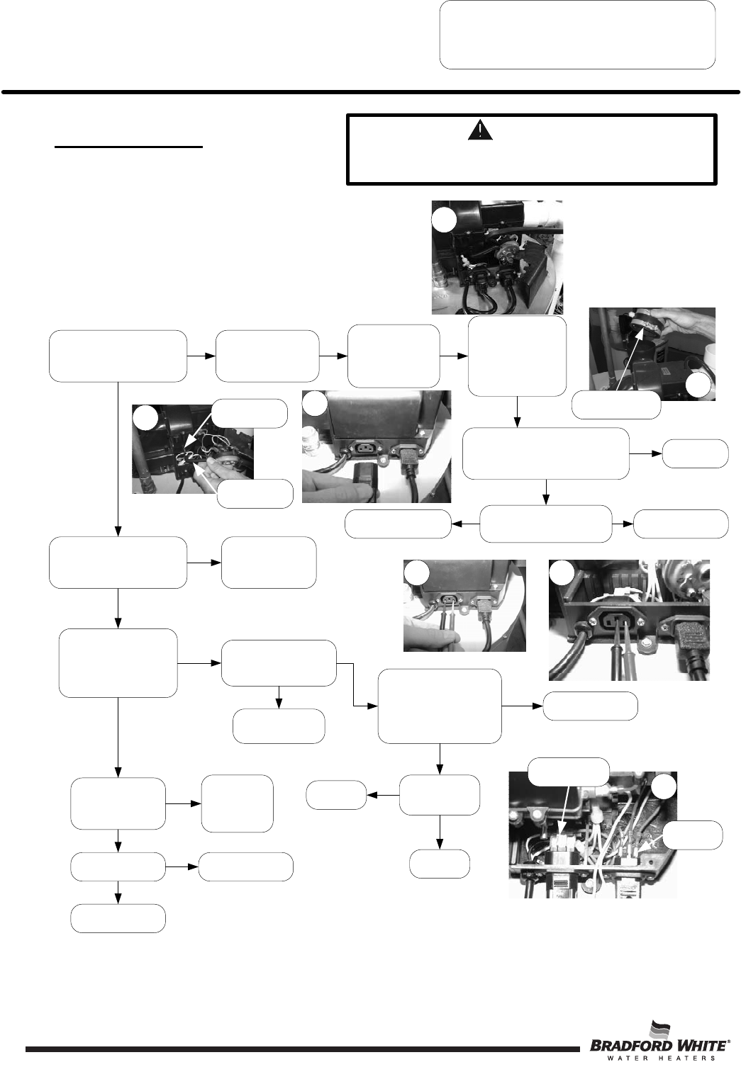
PDX SERVICE PROCEDURE IV
Blower Testing and Replacement
WARNING
115 volt potential exposure. Use caution when
making voltage checks to avoid personal injury.
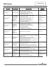
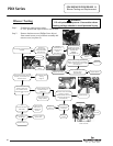
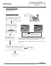
Blower Testing
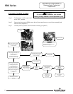
Is there 115VAC across
terminals shown in
photo 13 ?
Incorrect supply
voltage polarity
Determine
power source
problem and
correct.
Does blower energize Within 2
minutes?
Y
Disconnect cord set
shown in photo 9. Is
there 115VAC across
terminals shown in photo
12
N
See pressure switch
testing
Page 18
Is there 115 VAC at
wall outlet?
Check power cord
for damage.
Y
N
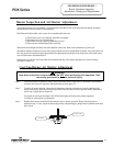
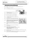
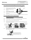
Disconnect
pressure switch
tubing from blower.
(see photo 13)
Connect
manometer to
pressure tap of
blower.
(see photo 11)
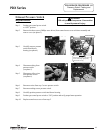
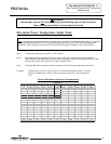
With blower running, and exhaust
adapter removed from top of blower,
is there a negative pressure of -2.30"
to -2.60" W.C.?
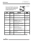
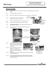
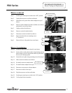
Step 1. Position gas control power switch
to “ON” position and adjust control to call for heat.
Step 2. Remove the three screws (Phillips Screw driver)
from control access cover on blower assembly and
remove cover (see photo 8).
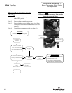
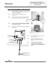
Reconnect cord set shown
in photo 8, is there
115VAC between blue wire
and green ground wire
(see photo 14)
Replace blower
Does cord set
have electrical
continuity?
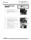
Disconnect vent
system from top of
blower and remove
exhaust vent
adapter.
(see photo 15)
Does blower energize after 2
minutes, run for 30 seconds
and shut down?
N
Is there 115vac across blue
and green wires
(see photo 14)
Blower OK
Y
Repair or replace
power cord
Replace blower
Y
N
N
N
N
Y
Y
Y
Y
N
Pressure switch
tubing
Pressure tap
Remove exhaust
adapter
Shown with pressure
switch removed.
Green ground
wire
Blue wire
Replace blower
Y
Determine voltage
problem and correct.
N
Page 20
8
9
10
12 13
14
11
Replace gas
control
Y
Replace
cord set
N
PDX Series
20