


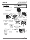
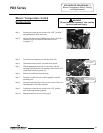
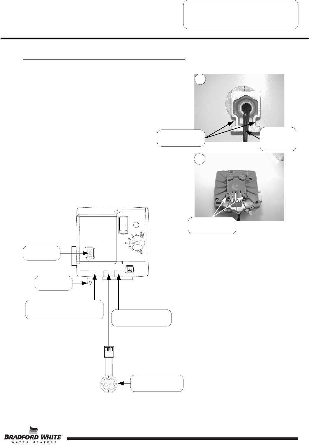
Gas Control Assembly to Thermal Well
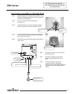
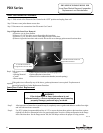
Step 6. Reconnect wire harnesses to gas control
per the illustration.
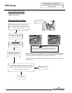
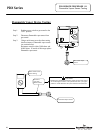
Step 7. Reconnect gas piping to gas control.
Restore gas supply and check for gas
leaks.
Step 8. To resume operation, follow the
instruction located on the lighting
instruction label or the lighting instruction
located in the installation and operation
manual.
5 pin
blower harness connection
3 pin
thermal well connection
Ground Wire
connection
Igniter/sensor
connection
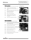
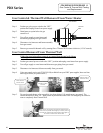
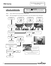
Thermal well flange
slots
Gas control Tabs
PDX SERVICE PROCEDURE VI
Gas Control & Thermal Well Testing
and Replacement
Page 27
22
23
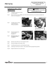
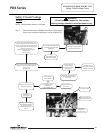
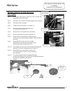
Step 1. Install threaded end of thermal well into tank. Be sure
thermal well flange is positioned as shown in photo 22
for proper control alignment.
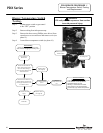
Step 2. Route wire leads back into relief opening.
(see photo 23)
Step 3. Align slots located on thermal well flange with tabs
located on back of gas control (see photo 22 & 23)
Step 4. Carefully push control back onto thermal well flange
as far as possible towards water heater. Slide control
down to lock into position.
Step 5. Install burner and connect pilot tubing and feedline nut
to gas control.
Route wires
through relief
opening
PDX Series
Flammable Vapor
Sensor
27