


5 68-0063—3
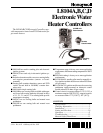
L8104A,B,C,D
INSTALLATION
Installation
WHEN INSTALLING THIS PRODUCT…
1. Read these instructions carefully. Failure to follow
them could damage the product or cause a hazardous
condition.
2. Check the ratings given in the instructions and on
the product to make sure the product is suitable for your
application.
3. Installer must be a trained, experienced service
technician.
4. After installation is complete, check out product
operation as provided in these instructions.
WARNING
EXPLOSION HAZARD.
CAN CAUSE PROPERTY DAMAGE,
SEVERE INJURY OR DEATH.
This product is for use only in a system with a
pressure relief valve.
CAUTION
Disconnect power supply before wiring to prevent
electrical shock or equipment damage.
IMPORTANT: Do not bend or pull on sensor leadwires
when temperature is below freezing to prevent leadwire
damage. Install L8104 only when temperature is above
32
°
F (0
°
C).
LOCATION AND MOUNTING
Sensing Bulb(s)
The water heater manufacturer usually provides a tap-
ping for the sensing bulb at a point where average water
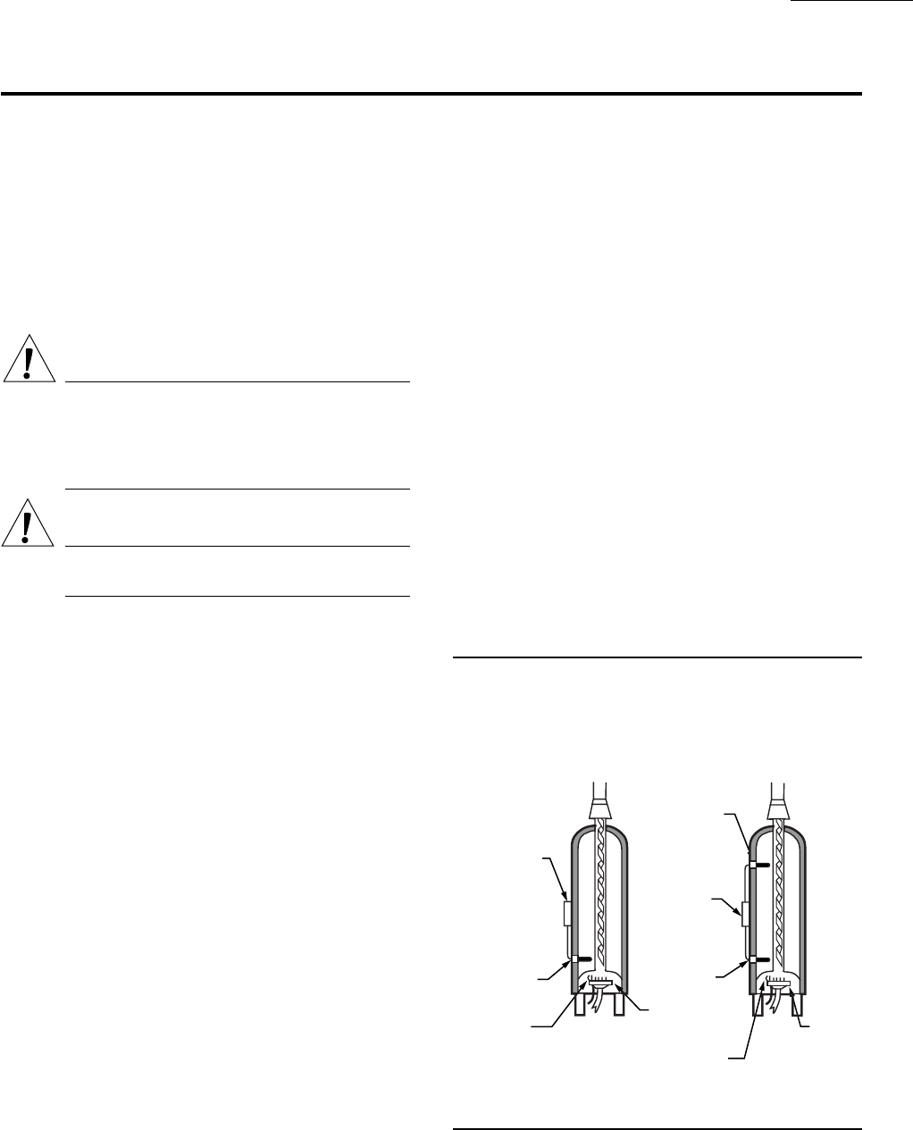
temperature can be measured. With L8104B,C, the bulb
containing the thermistor and ECO switch is usually mounted
in the tapping near the bottom of the heater, and the other
bulb is located near the top. See Fig. 4. Follow the heater
manufacturer instructions.
The sensing bulb can be installed in an immersion well
or directly immersed with a suitable compression fitting to
prevent leakage. Wells and fittings must be ordered sepa-
rately.
If an immersion well is used, the bulb should fit snugly
and should touch the bottom of the well for best temperature
response. Use heat-conductive compound (available in 4 oz
can as Honeywell part no. 107408) to fill the space between
the bulb and the well and improve heat transfer characteris-
tics. Make sure the bulb is held firmly in the well.
If the sensor is directly immersed, use a 3/8 in. x 1/2 in.
compression to M.I.P. coupling or O-ring and clamp to
prevent leaks and keep bulb leadwires dry.
Electronic Control Module
Locate the electronic control module on a wall or panel
in the wiring compartment of the water heater. The module
must be within easy reach of the sensor leadwires in a
location that is convenient for reading and changing the
temperature setting. Choose a location where the module
will not be exposed to water. An enclosure is recommended
to help protect the module. Mount the module with four no.
6 or 8 screws through the corner standoffs.
Remote Mount Potentiometer
Choose a location that is convenient for reading and
changing the temperature setting. Mount the potentiometer
from the back of a panel through a 3/8 in. hole and secure it
with a nut on the threaded shaft.
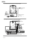
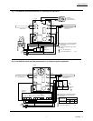
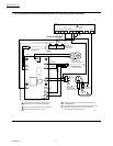
WIRING
IMPORTANT: For maximum trouble free operation, run
the sensing bulb leadwires separately from any other
current-carrying wires.
All wiring must comply with local codes and ordi-
nances. Disconnect power supply before beginning wiring.
Connect according to water heater manufacturer instruc-
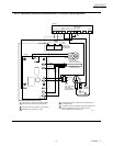
tions, if available, or use Fig. 5 through 10 as a guide.
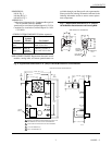
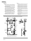
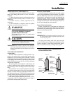
Fig. 4—Possible location of thermistor/ECO
bulb and thermistor bulb.
L8104A, D
L8104B, C
ELECTRONIC
CONTROL
MODULE
ENCLOSURE
SENSING
BULB
(WITH ECO)
THERMOCOUPLE
AND PILOT
BURNER
MAIN
BURNER
UPPER
SENSING BULB
(WITHOUT ECO)
THERMOCOUPLE
AND PILOT BURNER
MAIN
BURNER
LOWER
SENSING BULB
(WITH ECO)
ELECTRONIC
CONTROL
MODULE
ENCLOSURE
M132A