


L4188A,B; L4189A,B; L6188A-C; L6189A-C AQUASTAT® CONTROLLERS
68-0061—1 4
Accessories (order separately):
Capillary compression fittings.
Part No. 104484A: 1/2 in. NPT spud.
Part No. 104484B: 3/4 in. NPT spud.
Immersion well: Pressure rating 255 psi [1760 kPa].
Part No. 45900409-003B: 1/2 in. BSPT spud, 1 in.
insulation, 3-1/2 in. insertion.
Part No. 45900409-009B: 1/2 in. NPT spud, 1-1/2 in.
insulation, 3 in. insertion.
Part No. 45900409-010B: 3/4 in. NPT spud, 1-1/2 in.
insulation, 3 in. insertion.
Optional Specifications (Specify when ordering):
• Combination screw and 1/4 in. male quick-connect
terminals.
• High or low limit stop (models with knob only).
• Mounting bracket (remote bulb models only).
INSTALLATION
When Installing This Product...
1. Read these instructions carefully. Failure to follow them
could damage the product or cause a hazardous
condition.
2. Check the ratings given in the instructions and on the
product to make sure the product is suitable for your
application.
3. Installer must be a trained, experienced service
technician.
4. After installation is complete, check out product
operation as provided in these instructions.
CAUTION
Disconnect power supply before wiring to avoid
electrical shock or equipment damage.
Terminal connections must be inside an enclosure
that meets local electrical codes.
Location
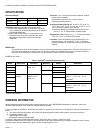
The equipment manufacturer generally provides a tapping for
insertion of the temperature controller sensing element. The
tapping should be located at a point where average system
temperature will be measured. Never locate the sensing
element close to a hot or cold water inlet or a steam coil, or
where the well’s pressure rating will be exceeded.
Turn off power and, if the system is filled, drain to a point below
the boiler tapping or wherever the sensing element is to be
located. If no tapping is provided, prepare one, properly
threaded, at the desired location.
If this is a remote bulb unit, the controller case can be mounted
in a panel or, with the optional bracket, on any flat surface.
Choose a location within reach of the sensing element. Allow
for gradual bends and some slack in the capillary.
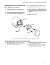
Mount the Immersion Well
1. Coat the well threads with a moderate amount of pipe
dope, leaving two end threads bare. Teflon
®
tape may
also be used.
2. Screw the immersion well into the tapping and tighten
securely.
3. Refill the system. Check for and correct any leaks.
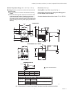
Fig. 2. Use good Piping Practice when Installing
Immersion Well.
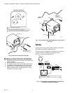
To Install Direct Mount Controller
1. Slide the sensing bulb all the way into the well. The metal
collar around the capillary should slip into the well spud.
2. Line up the case so the setting indicator is on top.
3. Tighten the setscrew in the well spud snugly against the
metal collar.
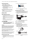
Fig. 3. The Direct Mount Model is held in place by the
Setscrew in the Well Spud.
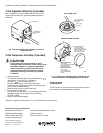
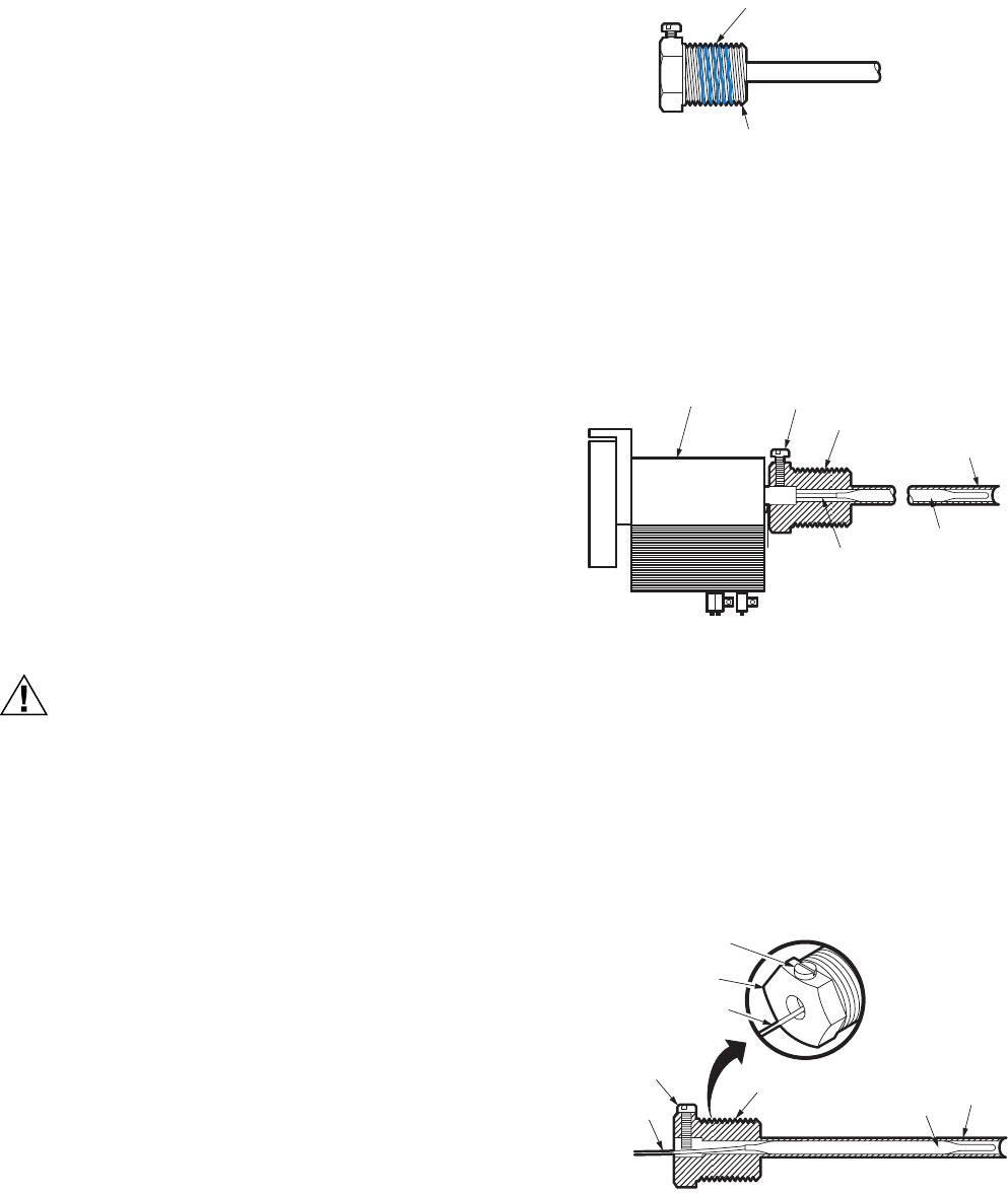
To Mount Remote Bulb Controller
Insert Sensing Bulb in Well
1. Slide sensing bulb into well. Make sure bulb rests
against the bottom of the well. Don’t bend the capillary
where it connects to the bulb.
2. Hold bulb in place and tighten setscrew all the way
down. It won’t fit tight against the capillary, but it will keep
the bulb from sliding out.
Fig. 4. The Setscrew keeps the Remote Sensing Bulb in
the Well.
USE MODERATE AMOUNT
OF PIPE COMPOUND
LEAVE 2 END THREADS BARE
M25415
CONTROLLER
SETSCREW
SPUD
WELL
BULB
CAPILLARY
METAL
COLLAR
M25416
SETSCREW
SPUD
CAPILLARY
CAPILLARY
SETSCREW
SPUD
BULB
WELL
M25417