Ratings: 10.5A maximum at 208 to
240 Vac, 50/60 Hz, 2500W. (To
determine baseboard wattage,
check the nameplate or
measure the length of the
baseboards the thermostat will
control. Generally, if the length of
the baseboards is more than ten
feet per thermostat, the wattage
is probably over 2500W. You
need to call an electrician.)
Not for use with central heating
systems or fan-forced heaters.
Do-it-yourself model.
YOUR HONEYWELL THERMOSTAT
Your new Honeywell CT1700 adjusts room temperature to
maximize comfort and energy savings by sensing light and
motion. It provides 15% to 23% energy savings compared to
nonprogrammable electric heating thermostats. The CT1700
replaces any two-wire, spst, line voltage thermostat used for
controlling electric baseboard heat.
CT1700A
ultrastat
™
MOTION-ACTIVATED
LINE VOLTAGE THERMOSTAT
Programmable control for baseboard heaters.
Temperature Setting Range: 44 °F to 80 °F [7 °C to 27 °C].
Motion Detection: Infrared detection up to 23 ft [7m]; 60 degrees vertical
and 110 degrees horizontal viewing angle.
Light Detection: Photoresistive element with adjustable light level
sensitivity.
Switching: Triac based (spst).
CONTENT SECTION
PREPARATION 1
THERMOSTAT FEATURES 2
REMOVE OLD THERMOSTAT 3
WIRE AND MOUNT NEW THERMOSTAT 4
CHECK fOUT THERMOSTAT 5
PROGRAMMING 6
Limited One-Year Warranty
Honeywell warrant this product to be free from defects in the workmanship or materials, under nor-
mal use and service, for a period of one (1) year from the date of purchase by the consumer. If, at any
time during the warranty period, the product is defective or malfunctions, Honeywell shall repair or
replace it (at Honeywell's option) within a reasonable period of time.
If the product is defective,
(i) return it, with a bill of sale or other dated proof of purchase, to the retailer from which you
purchased it, or
(ii) package it carefully, along with proof of purchase (including date of purchase) and a short
description of the malfunction, and mail it, postage prepaid, to the following address:
Honeywell Inc. in Canada: Honeywell Limited/Honeywell Limitée
Return Goods Department Product Services ON15-FFE
1050 Berkshire Lane 740 Ellesmere Road
Plymouth, MN 55441-4437 Scarborough, Ontario M1P 2V9
This warranty does not cover removal or reinstallation costs. This warranty shall not apply if it is
shown by Honeywell that the defect or malfunction was caused by damage which occurred while the
product was in the possession of a consumer.
Honeywell's sole responsibility shall be to repair or replace the product within the terms stated above.
HONEYWELL SHALL NOT BE LIABLE FOR ANY LOSS OR DAMAGE OF ANY KIND, INCLUDING
ANY INCIDENTAL OR CONSEQUENTIAL DAMAGES RESULTING, DIRECTLY OR INDIRECTLY,
FROM ANY BREACH OF ANY WARRANTY, EXPRESS OR IMPLIED, OR ANY OTHER FAILURE
OF THIS PRODUCT. Some states do not allow the exclusion or limitation of incidental or consequen-
tial damages, so this limitation may not apply to you.
THIS WARRANTY IS THE ONLY EXPRESS WARRANTY HONEYWELL MAKES ON THIS PROD-
UCT. THE DURATION OF ANY IMPLIED WARRANTIES, INCLUDING THE WARRANTIES OF MER-
CHANTABILITY AND FITNESS FOR A PARTICULAR PURPOSE, IS HEREBY LIMITED TO THE
ONE YEAR DURATION OF THIS WARRANTY. Some states do not allow limitations on how long an
implied warranty lasts, so the above limitation may not apply to you.
This warranty gives you specific legal rights, and you may have other rights which vary from state to
state.
If you have any questions concerning this warranty, please write our Customer Assistance Center,
Honeywell Inc., P.O. Box 524, Minneapolis, MN 55440-0524 or call 1-800-468-1502, Monday-Friday,
7:00 a.m. to 5:30 p.m., Central time. In Canada, write Retail Products ON15-02H, Honeywell Limited/
Honeywell Limitée, 740 Ellesmere Road, Scarborough, Ontario M1P 2V9.
1
PREPARATION
Proper installation of your
Honeywell thermostat will
occur if you follow instructions
step-by-step
. It is recom-
mended that as you read,
understand and complete each
step, you check √ it off with
pencil or pen.
Check thermostat suitabil-
ity for your home’s system
by reviewing the ratings listed on
the front of these instructions.
Make certain that your
heating system is
working, especially if it has
been inoperative for a length of
time. If the system does
not work, contact your local elec-
trician for assistance.
Carefully unpack your new
thermostat.
Save instructions, receipt
and proof-of-purchase.
J. H. • 12-93 • Printed in Canada • ©Honeywell Inc. 1993 • Form Number 69-0820
2
THERMOSTAT FEATURES
Loosen the screws
holding the thermostat
base to the electrical box and
lift away.
Disconnect wires from
the old thermostat. If
the old thermostat was not
mounted to a vertical outlet
box, install a box now.
Check the old wire
insulation for cracks,
nicks or fraying, and apply UL
Listed/CSA Certified electrical
tape where necessary, for
adequate insulation.
Retain the old thermo-
stat for reference later
and until your new thermostat
is functioning smoothly.
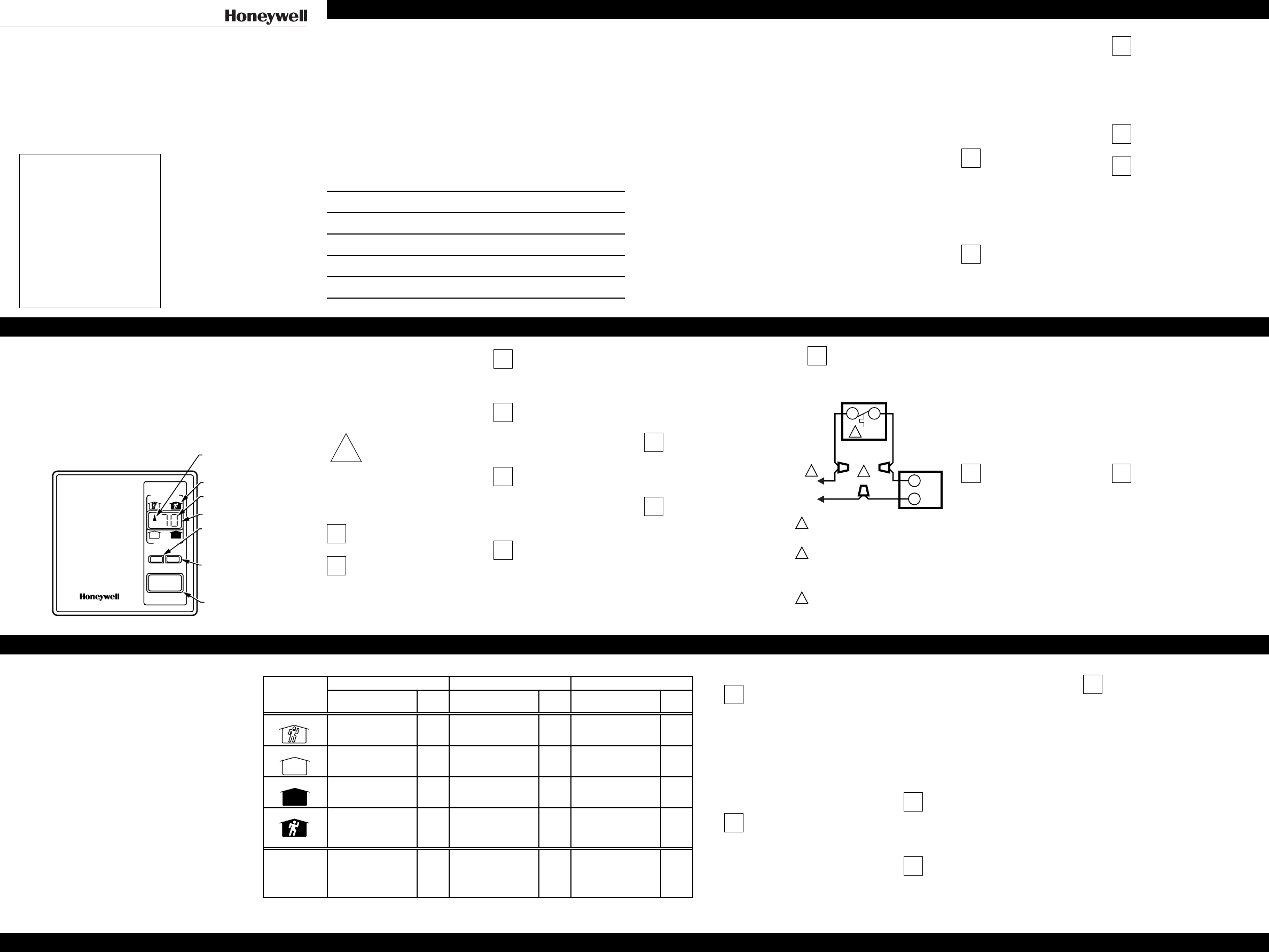
M9072
COMFORT
ECONO
SET SEL
MODE SYMBOLS
LCD DISPLAY
TEMPERATURE SETTING
SELECT KEY FOR
CHANGING FROM
MODE TO MODE
LIGHT SENSOR WINDOW
SET KEY FOR CHANGING
THE SETTINGS IN
MODES OR READING
ROOM TEMPERATURE
MODE INDICATOR
SHOWS WHICH MODE
IS OPERATING
!
CAUTION
To prevent electrical shock or
equipment damage, disconnect
power supply before beginning
installation.
Begin by turning off power
to the heating system.
Remove cover of old
thermostat—cover
normally snaps off when pulled
firmly from the bottom. If it
resists, check for a screw that
locks on the cover.
3
REMOVE
OLD
THERMOSTAT
4
WIRE AND
MOUNT NEW
THERMOSTAT
Remove the CT1700A
cover by grasping the top
or bottom edges and pulling
outward away from the thermo-
stat base.
Connect wires to the
thermostat, as shown in
the wiring diagram, using
approved solderless wire
connectors.
NOTE: Special service CO/ALR
wire connectors must be
used when connecting with
aluminum conductors;
otherwise, a fire hazard can
result.
Prebend and push the
wires into the outlet box.
Mount the thermostat on the
outlet box using the screws
provided.
CHECK OUT
THERMOSTAT
Turn on the power to the
heating system. The
thermostat will display “SC” for
15 seconds, showing the
system is operating properly. If
an “E” flashes continuously, the
thermostat is defective. Return
the thermostat for a replace-
ment unit.
“
Occupied-dark” indicator
will flash for two minutes
while the thermostat program is
being initialized. Next, the
actual operating program will
be displayed. (It takes three
minutes from turning on the
power for the programmed
temperature to be displayed.)
5
6
PROGRAMMING
Tap the SEL key to move between modes. The
display changes in the following order: occupied-
light, unoccupied-light, unoccupied-dark, occu-
pied-dark, L, F or C.
NOTE: To lessen temperature changes when an
occupant leaves an area, the CT1700 will not
change from an occupied to unoccupied
setting for 60 minutes (light setting) or for three
hours (dark setting). If you notice your pet
activating the program, cover up the lower half
of the sensor window or program temperature
changes for only light and not occupancy.
Sample Programs
KITCHEN LIVING OR FAMILY ROOM BEDROOM
Mode Remarks
Temp.
Setting Remarks
Temp.
Setting Remarks
Temp.
Setting
Occupied-light Set for a comfortable
temperature for eating or
cooking.
68° F
[20° C]
Set for a comfortable
temperature for reading or
watching TV.
68° F
[20° C]
Set for a comfortable
temperature for getting up
in the morning.
68° F
[20° C]
Unoccupied-light Set the temperature desired
when you are out of the
room in the daytime.
60° F
[15° C]
Set the temperature desired
when you are out of the
room in the daytime.
60° F
[15° C]
Set the temperature desired
when you are out of the
room in the daytime.
60° F
[15° C]
Unoccupied-dark Program for when no one
is using the kitchen.
60° F
[15° C]
Program for when no one
is using the room.
60° F
[15° C]
Program for when no one
is using the bedroom.
60° F
[15° C]
Occupied-dark This mode is primarily for
sleeping rooms. Set
temperature desired when
no one is using the kitchen.
60° F
[15° C]
This mode is primarily for
sleeping rooms. Set
temperature desired when
no one is using the room.
60° F
[15° C]
Set desired temperature for
sleeping.
62° F
[16° C]
LIGHT LEVEL Use the least sensitive
setting so the thermostat
does not sense the light
from an open refrigerator
door at night.
L3 Use the most sensitive
setting so the thermostat
will sense the tv or small
reading light.
L1 Use the average setting. L2
Fahrenheit or Celsius Temperature
Display
Select Fahrenheit or Celsius by
tapping the SEL key until F or C
appear in the LCD display. Tap the
SET key to select the setting.
Program Temperature Setting
NOTE: If programming in Fahrenheit,
only even numbered temperatures
(i.e., 66, 68, 70) can be selected.
The temperature setting range is
40° to 86° F [5° to 30° C].
Tap the SEL key until the
indicator on the LCD points to
the desired condition (i.e., occupied-
dark). Press the SET key to select the
desired temperature. Repeat for each
condition.
Program Light Level
Consider the ambient outdoor and
indoor lighting over a 24 hour period
when setting the light level. The three
light level settings are: L1—the most
sensitive so it is used when you want
the thermosat to respond to a low light
level, like the TV or reading light; L2—
average setting so it is used for most
rooms; L3—the least sensitive setting
so it is used in well-lit areas.
Tap the SEL key until the LCD
displays L1, L2 or L3. Tap the
SET key to change the light
setting.
Review Program
Tap the SEL key to scroll
between settings. If you want to
change any setting, tap the SET key
until the display shows the desired
setting.
Reading Current Temperature
Tap the SET key. The room
temperature and four indicators
will be displayed for about ten sec-
onds. The display range is 40° to 86°F
[5° to 30°C]. When the room tempera-
ture is warmer than 86° F [30° C], the
two upper indicators will be displayed.
When the room temperature is colder
than 40° F [5° C], the two lower
indicators will be displayed.
Loss of Power
The CT1700 maintains the program
during loss of power without batteries.
The display will go blank and when
power is restored, the display will go
through the steps in the CHECK OUT
THERMOSTAT section.
L1 T1
SOLDERLESS
CONNECTORS
L1
(HOT)
L2
3
2
ELECTRIC
HEATER
2
POWER SUPPLY. PROVIDE DISCONNECT
MEANS AND OVERLOAD PROTECTION
AS REQUIRED.
SPECIAL SERVICE CO/ALR SOLDERLESS
CONNECTORS MUST BE USED WHEN
CONNECTING WITH ALUMINUM
CONDUCTORS; OTHERWISE, A FIRE
HAZARD CAN RESULT.
TRIAC CONDUCTS EVERY 15 SECONDS
UNLESS ROOM TEMPERATURE IS ABOVE
SETPOINT.
3
1
1
M3643A


