08162 / TH114-A-240D / TL7235 69-2022 1/11/06 1/2
Non-programmable Thermostat - Installation and User Guide
This thermostat can be connected to an electric heater to control the
room temperature.
* The thermostat indicates how much heating is required to maintain the desired
temperature. For example, is displayed when heating is at 40 percent.
The configuration switches are located at the back of the control
module (faceplate).
2.1 Temperature Display (S1)
The S1 switch allows you to select
between °C and °F.
2.2 Model (S2)
The S2 switch allows you to control
the temperature using either the
thermostat’s built-in sensor or an
external sensor.
Turn off power to the heating system at the main electrical panel
to avoid electrical shock. The installation should be carried out
by an electrician.
High voltage thermostats must be installed onto an electrical
box.
For a new installation, choose a location about 5 ft. above the
floor and on an inside wall.
The thermostat must be installed on an inside wall facing the
heating system.
Avoid locations where there are air drafts (top of staircase, air
outlet), dead air spots (behind a door), direct sunlight or con-
cealed chimneys or stove pipes.
n Connect the power base wires to the power supply and load
using solderless connectors for copper wires.
o If you wish to use a remote controller such as the CT240 or
CT241 from Aube, insert the cable (use 18 to 22 gauge flexible
wires) into one of the two holes available below the terminal
board and connect to terminals 1 and 2 of the base.
p If you use an external sensor, insert the sensor wires through
one of the two holes below the terminals (figure 2) and connect
the wires to terminals 3 and 4 (no polarity).
q Push the excess length of the high-voltage wires back into the
electrical box.
r Secure the power base to the electrical box using the provided
screws.
s If necessary, set the configuration switches on the control mod-
ule (refer to the control module user guide).
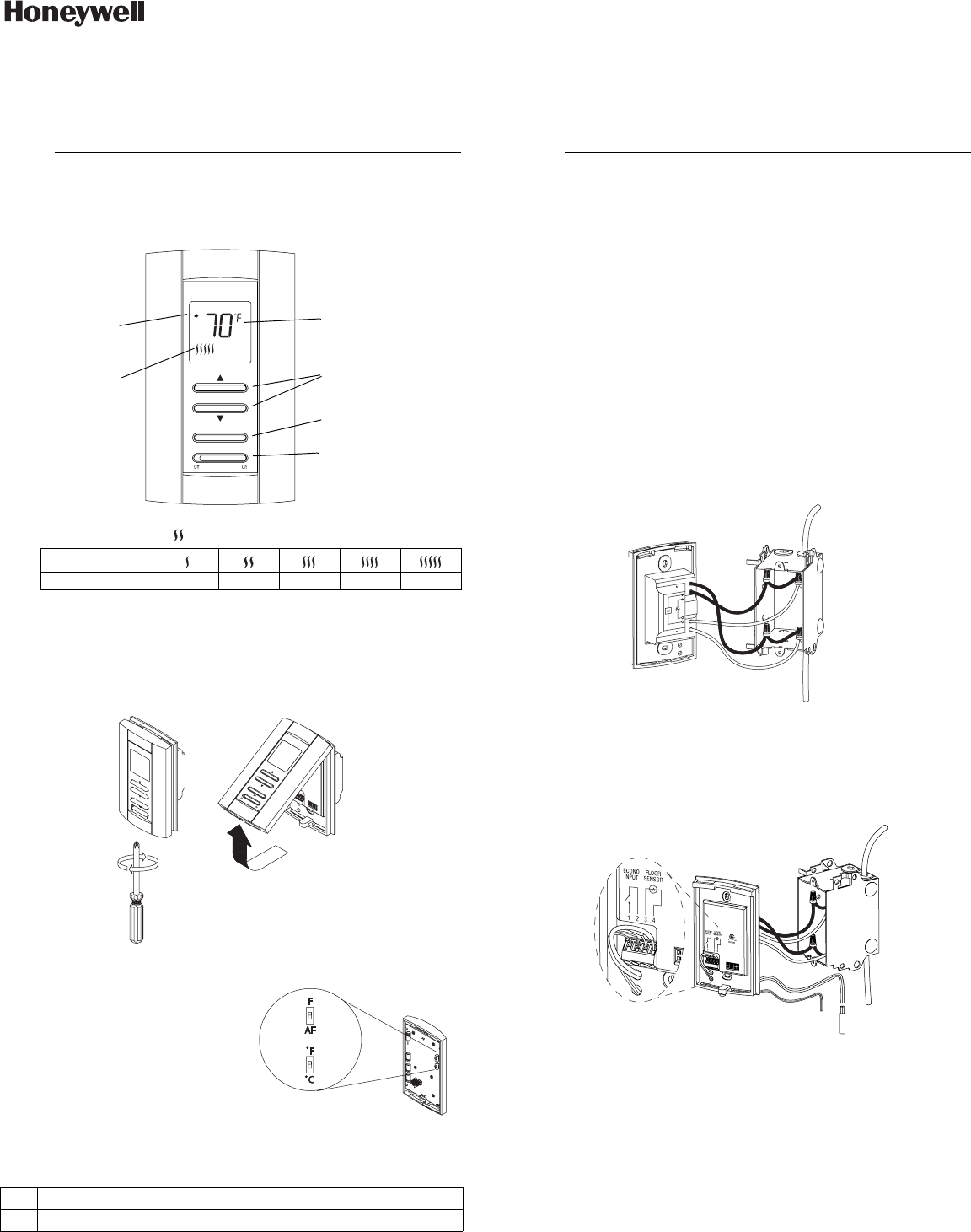
n
Description
1.
Display
% of heating 1 to 24% 25 to 49% 50 to 74% 75 to 99% 100%
o
Configuration
2.
AF: Use built-in sensor (external sensor not required)
F: Use external sensor (option)
Backlight button
Temperature
adjustment buttons
Set the switch to
Off to cut power to
the heater
Heating indicator *
Temperature
display
Appears when
the setpoint is
displayed
p
Installation
3.
Power
Load
08162
TH114-A-240D
TL7235
400-114-014-A_69-2022 (Cadet TL7235) ENG.fm Page 1 Wednesday, November 1, 2006 9:39 AM


